Land Cruiser URJ200 URJ202 GRJ200 VDJ200 - 1VD-FTV INTAKE / EXHAUST
INTAKE SYSTEM - ON-VEHICLE INSPECTION
| 1. CHECK INTAKE AIR CONTROL SYSTEM |
Check for leakage or clogging between the air cleaner housing and inlet turbocharger and between the outlet turbocharger and cylinder head.
| Condition | Operation |
| Clogged air cleaner | Replace element |
| Hoses collapsed or deformed | Repair or replace |
| Leakage from connections | Check each connection and repair |
| Cracks in components | Check and replace |
| 2. CHECK EXHAUST SYSTEM |
Check for leakage or clogging between the cylinder head and turbocharger inlet and between the turbocharger outlet and exhaust pipe.
| Condition | Operation |
| Deformed components | Repair or replace |
| Foreign material in passages | Remove |
| Leakage from components | Repair or replace |
| Cracks in components | Check and replace |
| 3. CHECK AIR INDUCTION SYSTEM |
- HINT:
- The illustration shows the areas that may draw in secondary air, which could lead to idling problems.
Check that the hoses, gaskets, clamps and O-rings are installed correctly.
Check for cracks, etc. in the hoses, gaskets and O-rings.

| *A | w/ Intercooler | - | - |

| *A | w/o Intercooler | - | - |

| *A | w/ EGR System | - | - |

| *A | w/o EGR System | *B | w/ Intercooler |
| *C | w/o Intercooler | - | - |
| 4. CHECK BOOST PRESSURE |
Connect the intelligent tester to the DLC3.
Start the engine and turn the tester on.
Warm up the engine.
- HINT:
- Be sure to perform the inspection when the engine coolant temperature is between 75 and 90°C (167 and 194°F).
Enter the following menus: Powertrain / Engine / Data List / VN Turbo.

Take a snapshot of the Data List items with the intelligent tester shown in the illustration.
| *1 | Snapshot Record Button |
- HINT:
Compare MAP with Target Booster Pressure.
- Standard:
- MAP is within 35 kPa of Target Booster Pressure when accelerating with accelerator pedal fully depressed.
- HINT:
Warm up the engine.
- HINT:
- Be sure to perform the inspection when the engine coolant temperature is between 75 and 90°C (167 and 194°F).
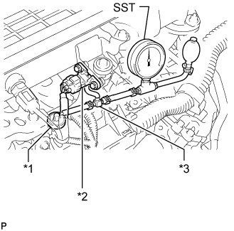
Using a 3-way connector, connect SST (turbocharger pressure gauge) between the diesel turbo pressure sensor (manifold absolute pressure sensor) and the gas filter.
- SST
- 09992-00242
| *1 | Gas Filter |
| *2 | Diesel Turbo Pressure Sensor |
| *3 | 3-Way Connector |
Fully apply the parking brake and chock the 4 wheels.
for Manual Transmission:
While depressing the clutch pedal, fully depress the accelerator pedal. Measure the boost pressure at maximum engine speed (4700 to 4900 rpm).
for Automatic Transmission:
Move the shift lever to P or N, and then fully depress the accelerator pedal. Measure the boost pressure at maximum engine speed (4700 to 4900 rpm).
- Standard Pressure (Gauge Pressure):
- 30 to 60 kPa (0.30 to 0.61 kgf/cm2, 4.3 to 8.7 psi)
If the pressure is lower than the standard, the following problems may be present.
The turbocharger sub-assembly or ECM is malfunctioning.
The turbocharger sub-assembly or turbo motor driver is malfunctioning.
If the pressure is higher than the standard, check the turbocharger and/or boost control components (turbo motor driver, pressure sensor, vacuum hose, wire harness, etc.).
Chart showing the suspected trouble areas when the pressure is lower than the standard.
- HINT:
| Item | MAP (Absolute pressure inside intake manifold) | MAF (Intake airflow rate) | Accel Position | Actual Throttle Position (#1, #2) | Actual EGR Valve Pos. (#1, #2) | EGR Close Lrn. Status (#1, #2) (EGR valve fully closed position learning status) | w/o DPF: Fuel Press w/ DPF: Common Rail Pressure | Injection Feedback Val #1 (to #8) |
| Values taken from an actual normal vehicle *1 | - | 228 g/sec. | 99% or more | w/o DPF: 0% | 0% | w/o DPF: OK | - | -3 to +3 mm3/st |
| w/ DPF: 100% | w/ DPF: - | |||||||
| Values which represent a malfunction *1 | MAP is below Target Booster Pressure by 35 kPa or more | MAF is less than 190 g/sec. | Accel Position is not fully depressed position *2 | Actual Throttle Position (#1, #2) is not within 10% of Target Throttle Position (#1, #2) | Actual EGR Valve Pos. (#1, #2) is more than 10% *3 | w/o DPF: NG (Determined after performing learning) | Fuel Pressure is below Target Common Rail Pressure by 10 MPa or more (Check while condition steady) | Outside of above range |
| w/ DPF: - | ||||||||
| Turbocharger | ○ | ○ | - | - | - | - | - | - |
| EGR valve does not close or has problem with movement | ○ | ○ | - | - | ○ (Problem with EGR valve movement) *4, *5 | ○ (EGR valve does not close) *4, *5 | - | - |
| Problem with diesel throttle movement | ○ (Intake airflow decreases) | ○ | - | ○ | - | - | - | - |
| Accelerator pedal cannot be fully depressed or problem with accelerator pedal position sensor exists | - | ○ | ○ | - | - | - | - | - |
| Intake air system leakage or blockage | ○ | ○ | - | - | - | - | - | - |
| Exhaust gas leakage before turbocharger or blockage | ○ | ○ | - | - | - | - | - | - |
| Manifold absolute pressure sensor | ○ | ○ | - | - | - | - | - | - |
| Manifold absolute pressure sensor hose is disconnected | ○ | ○ | - | - | - | - | - | - |
| Mass air flow meter sub-assembly | - | ○ | - | - | - | - | - | - |
| Fuel system (injector, supply pump or common rail) | ○ | ○ | - | - | - | - | ○ (Fuel injector leakage, decrease in pressure discharge valve relief pressure or valve is stuck) | ○ *6 |
- HINT:
DTC P0400 (Bank 1, Bank 2) or P042E (for Bank 1) or P045E (for Bank 2) may be stored at this time. If the actual EGR valve position follows the target EGR valve position slowly, a feeling of hesitation may occur.
DTC P0400 (for Bank 1) or P1248 (for Bank 2) may be stored at this time. If the actual EGR valve position follows the target EGR valve position slowly, a feeling of hesitation may occur.
| 5. CHECK TURBOCHARGER SUB-ASSEMBLY |
- CAUTION:
Make sure that the DC motors connector is properly connected.

Check the motor movement when turning the ignition switch to ON, when starting the engine, and then when turning the ignition switch off.
| *a | Ignition switch ON |
| *b | Engine idling |
| *c | *b → *c → *d: Turn the ignition switch off at idling |
| *d | Ignition switch off |
If the result is not as specified, check the ECM (w/ DPF: , w/o DPF: ) and/or turbo motor driver (w/ DPF: , w/o DPF: ).