Land Cruiser URJ200 URJ202 GRJ200 VDJ200 - 1UR-FE FUEL
FUEL SUB TANK - INSTALLATION
| 1. INSTALL FUEL TANK TO FILLER PIPE HOSE |

Install the hose to the fuel sub tank as shown in the illustration.
| *a | Tank Side Mark |
| *b | Hose Side Mark |
- HINT:
| *a | Stopper |
| 2. INSTALL NO. 3 FUEL HOSE |
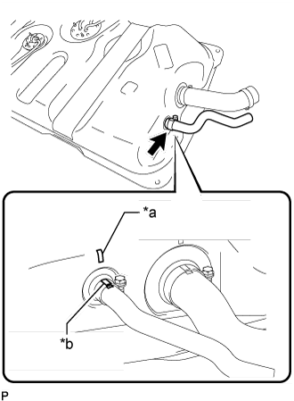
Install the fuel hose to the fuel sub tank as shown in the illustration.
| *a | Tank Side Mark |
| *b | Hose Side Mark |
- HINT:
| *a | Stopper |
| 3. INSTALL FUEL TANK BREATHER HOSE |
Install the breather hose to the fuel sub tank.
| 4. INSTALL FUEL AND EVAPORATION VENT TUBE SUB-ASSEMBLY |
Install a new gasket to the fuel and evaporation vent tube.
Install the fuel and evaporation vent tube with the 6 bolts.
- Torque:
- 3.5 N*m{ 36 kgf*cm, 31 in.*lbf}
| 5. INSTALL FUEL TANK EVAPORATION VENT TUBE SUB-ASSEMBLY |
except G.C.C. Countries:
Install the 2 fuel tank evaporation vent tubes.
for G.C.C. Countries:
Install the fuel tank evaporation vent tube.
| 6. INSTALL FUEL HOSE |
Install the fuel hose.
| 7. INSTALL FUEL SENDER GAUGE ASSEMBLY |
Install a new gasket to the sender gauge.
- NOTICE:
- Be careful not to bend the arm of the fuel sender gauge.
Install the sender gauge with the 5 screws.
- Torque:
- 1.5 N*m{ 15 kgf*cm, 13 in.*lbf}
| 8. INSTALL FLOOR NO. 3 WIRE |
Attach the wire harness clamp to the fuel sub tank.
Connect the sender gauge connector.
| 9. INSTALL FUEL SUB TANK SUB-ASSEMBLY |
Set the fuel sub tank on an engine lifter and raise the fuel sub tank.
Connect the 2 fuel tank bands with the 2 bolts.
- Torque:
- 40 N*m{ 408 kgf*cm, 30 ft.*lbf}
Connect the floor No. 3 wire connector.
Attach the 3 wire harness clamps.
| 10. CONNECT FUEL TANK TO FILLER PIPE HOSE |
Connect the hose to the filler pipe.
| 11. CONNECT NO. 3 FUEL HOSE |
Connect the fuel hose to the filler pipe.
| 12. CONNECT FUEL TANK BREATHER HOSE |
Connect the breather hose to the filler pipe.
| 13. CONNECT FUEL HOSE |
Connect the fuel hose.
| 14. CONNECT FUEL TANK EVAPORATION VENT TUBE SUB-ASSEMBLY |
except G.C.C. Countries:
Connect the 2 fuel tank evaporation vent tubes.
for G.C.C. Countries:
Connect the fuel tank evaporation vent tube.
| 15. INSTALL FUEL TANK CAP ASSEMBLY |
| 16. INSTALL NO. 1 SPARE WHEEL STOPPER |
Install the spare wheel stopper with the 2 bolts.
- Torque:
- 32 N*m{ 326 kgf*cm, 24 ft.*lbf}
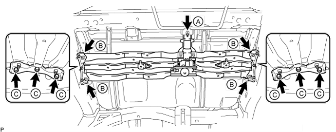
| 17. INSTALL SPARE WHEEL CARRIER CROSSMEMBER AND SPARE WHEEL CARRIER BRACKET |
Install the spare wheel carrier crossmember and 2 brackets to the vehicle with the 6 bolts labeled C.
- Torque:
- for bolt C:
- 20 N*m{ 204 kgf*cm, 15 ft.*lbf}
Temporarily install the bolt labeled A, and then tighten the bolt labeled A and bolts labeled B.
- Torque:
- for bolt A:
- 29 N*m{ 296 kgf*cm, 21 ft.*lbf}
- for bolt B:
- 20 N*m{ 204 kgf*cm, 15 ft.*lbf}
| 18. INSTALL TAILPIPE ASSEMBLY |
Install a new gasket to the center exhaust pipe.
Install the tailpipe to the 2 exhaust pipe supports.
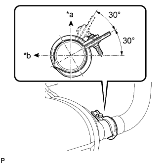
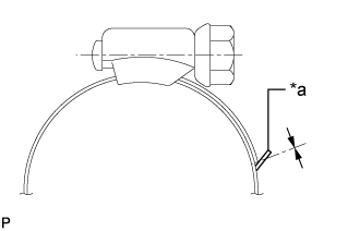
Install a new clamp.
- Torque:
- 32 N*m{ 326 kgf*cm, 24 ft.*lbf}
| *a | Top |
| *b | LH Side |
- HINT:
- Install the clamp within the angle range shown in the illustration.
| 19. CONNECT CABLE TO NEGATIVE BATTERY TERMINAL |
- NOTICE:
- When disconnecting the cable, some systems need to be initialized after the cable is reconnected ().
| 20. INSPECT FOR FUEL LEAK |
Make sure that there are no fuel leaks after performing maintenance on the fuel system.
Connect the GTS to the DLC3.
Turn the engine switch on (IG) and turn the GTS on.
- NOTICE:
- Do not start the engine.
Enter the following menus: Powertrain / Engine and ECT / Active Test / Control the Fuel Pump / Speed.
Check that there are no leaks from the fuel system.
If there are fuel leaks, repair or replace parts as necessary.
Turn the engine switch off.
Disconnect the GTS from the DLC3.
| 21. INSPECT FOR EXHAUST GAS LEAK |
| 22. INSTALL SPARE TIRE |