Land Cruiser URJ200 URJ202 GRJ200 VDJ200 - 1GR-FE FUEL
FUEL PUMP (for Double Tank Type) - INSTALLATION
| 1. INSTALL FUEL SUCTION WITH PUMP AND GAUGE TUBE ASSEMBLY |
Apply a light coat of gasoline or grease to a new gasket, and install it to the fuel tank.

Install the fuel suction with pump and gauge tube into the fuel tank.
| *1 | Protrusion |
| *2 | Groove |
 | Front |
- NOTICE:
- Be careful not to bend the arm of the fuel sender gauge.
- HINT:
- Align the protrusion of the fuel suction with pump and gauge tube with the groove of the fuel tank.
Put the retainer on the fuel tank. While holding the fuel suction with pump and gauge tube, tighten the retainer one complete turn by hand.
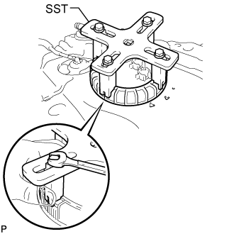
Set SST on the retainer.
- SST
- 09808-14030
- HINT:
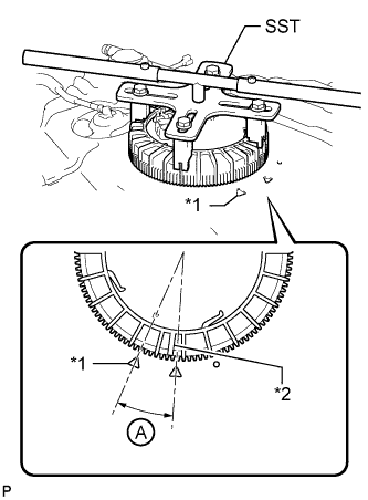
Using SST, tighten the retainer until the mark on the retainer is within range A on the fuel tank as shown in the illustration.
- SST
- 09808-14030
| *1 | Fuel Tank Side Mark |
| *2 | Retainer Side Mark |
- HINT:
- Fit the tips of SST onto the ribs of the retainer.
| 2. INSTALL FUEL TANK MAIN TUBE, FUEL TANK RETURN TUBE AND NO. 2 FUEL TANK MAIN TUBE SUB-ASSEMBLY |
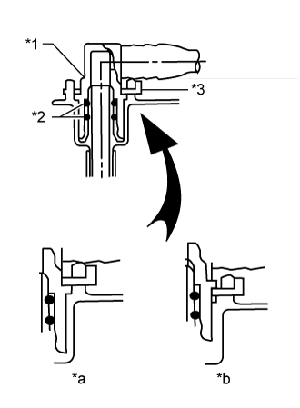
Install the 3 fuel tank tubes with the 3 tube joint clips.
- NOTICE:
| *1 | Fuel Tube Joint |
| *2 | O-Ring |
| *3 | Tube Joint Clip |
| *a | CORRECT |
| *b | INCORRECT |
for G.C.C. Countries:
Attach the 2 clamps and install the No. 2 fuel tank main tube sub-assembly.
Attach the clamp and install the fuel tank return tube sub-assembly.
Attach the clamp and install the fuel tank main tube sub-assembly.
except G.C.C. Countries:
Attach the 2 clamps and install the No. 2 fuel tank main tube sub-assembly.
Attach the clamp and install the fuel tank return tube sub-assembly.
Attach the clamp and install the fuel tank main tube sub-assembly.
| 3. INSTALL FUEL TANK SUB-ASSEMBLY |
()