Land Cruiser URJ200 URJ202 GRJ200 VDJ200 - 1VD-FTV ENGINE CONTROL
CHECK WIRE HARNESS AND CONNECTION IN ENGINE COMPARTMENT
READ OUTPUT DTC (RELATING TO ENGINE)
TAKE SNAPSHOT DURING IDLING (PROCEDURE 3)
CHECK DATA LIST (ENGINE SPEED)
CHECK DATA LIST (INJECTION FEEDBACK VAL #1 TO #8 AND INJECTION VOLUME)
INSPECT INJECTOR COMPENSATION CODE
PERFORM ACTIVE TEST USING GTS (CONTROL THE SELECT CYLINDER FUEL CUT)
REPLACE INJECTOR ASSEMBLY OF MALFUNCTIONING CYLINDER
CLEAN FUEL FILTER CASE AND REPLACE FUEL FILTER
REGISTER INJECTOR COMPENSATION CODE AND PERFORM PILOT QUANTITY LEARNING
REPAIR OR REPLACE HARNESS AND CONNECTOR
CHECK AND REPAIR ENGINE ASSEMBLY
CHECK DATA LIST (COMMON RAIL PRESSURE AND TARGET COMMON RAIL PRESSURE)
REPLACE FUEL SUPPLY PUMP ASSEMBLY (SUCTION CONTROL VALVE)
PERFORM FUEL SUPPLY PUMP INITIALIZATION
REPAIR OR REPLACE CLOGGED FUEL LINE
REMOVE DEPOSIT (EGR VALVE ASSEMBLY)
PERFORM PILOT QUANTITY LEARNING (DETAIL)
CHECK ROUGH IDLING OR EXCESSIVE ENGINE VIBRATIONS
CHECK AND REPLACE ENGINE MOUNTING INSULATOR
CONFIRM WHETHER MALFUNCTION HAS BEEN SUCCESSFULLY REPAIRED
ECD SYSTEM (w/ DPF) - Rough Idling or Excessive Engine Vibrations
DESCRIPTION
| Malfunction Condition | Main Trouble Area | Related Trouble Area |
Rough idling or juddering due to abnormal combustion Juddering when vehicle is starting due to clutch system malfunctions | Injector assembly malfunctions Injector sliding malfunction Injector stuck closed Injector stuck open Deposits in injector Injector circuit malfunction | Injector compensation code Fuel leak Engine mounting insulator Intake air system leakage Intake air system blockage EGR system Throttle valve system Mass air flow meter Suction control valve (fuel supply pump assembly) Fuel pressure sensor (common rail assembly (for bank 1)) No. 1 or No. 2 injector driver (P062D, P062E stored simultaneously) Low quality fuel Vehicle modifications Fuel filter air bleed problem Accessory problem (A/C, generator, etc.) ECM |
- HINT:
| Faults and Symptoms of Common Rail Diesel Components |
Engine Control
| Main fault | Decrease in performance (foreign matter is stuck) |
| Symptoms | Lack of power, black smoke |
| Data List | MAF |
|
| Main fault | Glow system malfunction |
| Symptoms | Difficult to start, rough idle, knocking, white smoke (when cold) |
| Data List | Check the glow plug indicator light |
| Diagnostic Point | Measure the resistance of the glow plug |
| Main fault | Loss of compression |
| Symptoms | Rough idle (lack of power always) |
| Data List | Engine Speed of Cyl When cranking during the "Check the Cylinder Compression" Active Test, if there is a high speed cylinder, approx. 100 rpm more than the other cylinders, that cylinder may lose compression. When an Injector Feedback Val is more than 3 mm3/st, there may be a malfunction in the corresponding cylinder. |
Diesel Injection
| Main fault | - |
| Symptoms | Difficult to start, engine stalling, rough idle, lack of power |
| Data List | Common Rail Pressure, Target Common Rail Pressure, Target Pump SCV Current Common Rail Pressure is within 5000 kPa of Target Common Rail Pressure during idling with the engine warmed up (engine coolant temperature is higher than 70°C (158°F)). If the fuel pressure is 20000 kPa below the target common rail pressure, then a lack of power will be felt. If the fuel pressure is below 25000 kPa, then idling will be rough.
The fuel pressure changes at engine start, but is approx. 25000 kPa at engine start after the engine is warmed up. When Target Pump SCV Current is 3000 mA or higher, the suction control valve has a tendency to become stuck. |
| Diagnostic Trouble Code | Even if Common Rail Pressure is below Target Common Rail Pressure, a DTC will not be stored. |
| Main fault | Blockage |
| Symptoms | Difficult to start, engine stalling, rough idle, lack of power |
| Data List | Common Rail Pressure, Target Common Rail Pressure Common Rail Pressure is within 5000 kPa of Target Common Rail Pressure during idling with the engine warmed up (engine coolant temperature is higher than 70°C (158°F)). If the fuel pressure is 20000 kPa below the target common rail pressure, then a lack of power will be felt. If the fuel pressure is below 25000 kPa, then idling will be rough.
|
| Diagnostic Trouble Code | Even if Common Rail Pressure is below Target Common Rail Pressure, a DTC will not be stored. |
| Main fault | Blockage |
| Symptoms | Rough idle, lack of power, black smoke, white smoke, knocking |
| Data List | Injection Feedback Val When an Injector Feedback Val is more than 3 mm3/st, there may be a malfunction in the corresponding cylinder. This value can be read after idling for 1 minute. |
| Main fault | Circuit fault: The fuel injector assembly does not open. |
| Symptoms | Difficult to start, rough idle, lack of power, black smoke, white smoke, knocking |
| Data List | Same as injector assembly |
| Diagnostic Trouble Code | When the injector driver has a fault, some DTCs may be stored. |
| Main fault | Open circuit, decrease in performance (foreign matter is stuck) |
| Symptoms | Difficult to start, rough idle, engine stall, lack of power |
| Data List | Common Rail Pressure, Target Common Rail Pressure Slowly raise the engine speed from idling to 3000 rpm with the vehicle stopped and check that Common Rail Pressure follow Target Common Rail Pressure. If the fuel pressure sensor malfunctions, the actual fuel pressure may deviate from the target fuel pressure (either Common Rail Pressure decreases to a value less than Target Common Rail Pressure). |
| Diagnostic Trouble Code | When the fuel pressure sensor has a fault, some DTCs may be stored. |
| Main fault | - |
| Symptoms | Difficult to start, rough idle (especially when cold) |
Diesel EGR
| Main fault | Does not move smoothly Does not close completely |
| Symptoms | Rough idle EGR valve stuck closed: A loud turbocharger sound. EGR valve stuck open: Difficult to start (does not stall), black smoke, lack of power (if there is an excess in the quantity of EGR and there is a heavy load, when the vehicle starts moving, a lack of power will be felt). |
| Data List | Actual EGR Valve Pos, Actual EGR Valve Pos #2, Target EGR Valve Pos, Target EGR Valve Pos #2 Generally, Actual EGR Valve Pos = Target EGR Valve Pos +/-5% (fully closed: 0%, fully open: 100%). Using the EGR valve Active Test, check whether Actual EGR Valve Pos follows Target EGR Valve Pos (the engine coolant temperature and intake air temperature should be considered when a malfunction occurs). EGR valve is fully closed when the engine switch is turned to on (IG) (engine stopped). EGR valve opens to the halfway point at idling after the engine is warmed up. When leaving the vehicle idling, the normal range of EGR Close Lrn. Val. is 3.5 to 4.5 V. In cases when EGR Close Lrn. Val. is out of the normal range (3.5 to 4.5 V), it is possible that the EGR valve cannot completely close. |
Diesel Throttle
| Main fault | Stuck, does not move smoothly |
| Symptoms | Stuck closed: Lack of power, difficult to start, rough idle, engine stall, black smoke. These may occur when stuck almost fully closed. Stuck open: Turbocharger sound increases. When the engine is stopped, engine vibrations may occur. |
| Data List | Actual Throttle Position, Actual Throttle Position #2 100%: Fully open 0%: Fully closed When the engine switch is turned to on (IG) (the engine is stopped), the diesel throttle is fully open. When idling, the diesel throttle is at the halfway point. When the engine switch is turned from on (IG) to off, the throttle is fully closed temporarily. |
| Data List Related to Rough Idling |
INSPECTION PROCEDURE
- NOTICE:
After replacing the fuel supply pump assembly, the ECM needs initialization ().
| 1.CHECK WIRE HARNESS AND CONNECTION IN ENGINE COMPARTMENT |
Check the wire harness and connector connections of common rail system components.
- OK:
- The wire harnesses and connectors are connected securely.
- HINT:
- The engine may have problems when there is an intermittent disconnection in a circuit related to the fuel pressure sensor, crankshaft position sensor, engine coolant temperature sensor, etc.
|
| ||||
| OK | |
| 2.READ OUTPUT DTC (RELATING TO ENGINE) |
Connect the GTS to the DLC3.
Turn the engine switch on (IG) and turn the GTS on.
Enter the following menus: Engine and ECT / Trouble Codes.
Read the pending DTCs.
| Result | Proceed to |
| No DTCs are output | A |
| Engine related DTCs are output | B |
- HINT:
- If only DTC P1605 is output, proceed to step 4.
|
| ||||
| A | |
| 3.TAKE SNAPSHOT DURING IDLING (PROCEDURE 3) |
Connect the GTS to the DLC3.
Start the engine and turn the GTS on.
Warm up the engine (engine coolant temperature is 70°C (158°F) or higher).
Enter the following menus: Engine and ECT / Data List / All Data.
Take a snapshot when idling with no load after the engine is warmed up and when the problem is occurring.
- HINT:
| NEXT | |
| 4.CHECK WHITE SMOKE |
Start the engine.
Fully depress the accelerator pedal, and then release it.
Check whether white smoke is emitted when racing the engine.
- NOTICE:
- Be sure not to check for white smoke indoors.
- HINT:
- Depending on whether there is oil mixed with the fuel, or whether there is unburned fuel present, the smell of the exhaust gas differs. When oil is mixed in, the exhaust gas smells like burning oil.
| Result | Proceed to |
| White smoke is not emitted | A |
| White smoke is emitted | B |
|
| ||||
| A | |
| 5.CHECK DATA LIST (ENGINE SPEED) |
Check engine speed in the snapshot taken in procedure 3 when the engine was idling.
| Result | Proceed to |
| Change in engine speed coincides with air conditioning system operation | B |
| Except above | A |
|
| ||||
| A | |
| 6.CHECK DATA LIST (INJECTION FEEDBACK VAL #1 TO #8 AND INJECTION VOLUME) |
Check Injection Feedback Val # in the snapshot taken in procedure 3 when the engine was idling.
| Result | Proceed to |
| Injection Feedback Val for at least one cylinder is more than +3 mm3/st and engine vibration is abnormally large | A |
| Except above | B |
- HINT:
|
| ||||
| A | |
| 7.INSPECT INJECTOR COMPENSATION CODE |
Read the injector compensation code ().
- OK:
- Compensation codes stored in the ECM match compensation codes of the installed injector assemblies.
|
| ||||
| OK | |
| 8.PERFORM ACTIVE TEST USING GTS (CONTROL THE SELECT CYLINDER FUEL CUT) |
- HINT:
- Use this Active Test to determine the malfunctioning cylinder.
Connect the GTS to the DLC3.
Start the engine and turn the GTS on.
Enter the following menus: Engine and ECT / Active Test / Control the Select Cylinder Fuel Cut / #1 to #8.
Check the 8 cylinders in sequence to identify any faulty cylinders by performing the power-balance inspection.
- HINT:
| NEXT | |
| 9.REPLACE INJECTOR ASSEMBLY OF MALFUNCTIONING CYLINDER |
Replace the injector assembly of the malfunctioning cylinder ().
- NOTICE:
| NEXT | |
| 10.CLEAN FUEL FILTER CASE AND REPLACE FUEL FILTER |
Clean the fuel filter case and replace the fuel filter.
- HINT:
- Be sure to clean the inside of the fuel filter case as the fuel injectors may not operate properly if the fuel filter is installed with foreign matter remaining inside the fuel filter case.
| NEXT | |
| 11.BLEED AIR FROM FUEL SYSTEM |
Bleed the air from the fuel system ().
Perform PM forced regeneration ().
- HINT:
- When fuel lines are disconnected, air may enter the fuel lines, leading to engine starting trouble. Therefore, perform forced regeneration and bleed the air from the fuel lines.
| NEXT | |
| 12.REGISTER INJECTOR COMPENSATION CODE AND PERFORM PILOT QUANTITY LEARNING |
Register the injector compensation code ().
Perform the injector pilot quantity learning ().
|
| ||||
| 13.REPAIR OR REPLACE HARNESS AND CONNECTOR |
Repair or replace the harness or connector.
|
| ||||
| 14.CHECK AND REPAIR ENGINE ASSEMBLY |
Check the following items and repair the malfunctioning part if necessary.
Check the cylinder compression pressure ().
|
| ||||
| 15.CHECK AIR CONDITIONING SYSTEM |
Check the air conditioning system.
- HINT:
|
| ||||
| 16.CHECK DATA LIST (COMMON RAIL PRESSURE AND TARGET COMMON RAIL PRESSURE) |
Check the engine speed in the snapshot taken in procedure 3 when the engine was idling after having been warmed up.
| Result | Proceed to |
| Difference between Common Rail Pressure and Target Common Rail Pressure is 5000 kPa (51.0 kgf/cm2, 725 psi) or more | A |
| Except above | B |
|
| ||||
| A | |
| 17.INSPECT CLOGGED FUEL PIPE |
Connect the GTS to the DLC3.
Start the engine and turn the GTS on.
Enter the following menus: Engine and ECT / Data List / Diesel Injection.
With no load after the engine is warmed up, take a snapshot when idling and when the vehicle is accelerating with the accelerator pedal fully depressed in 2nd gear.
Check the Target Common Rail Pressure and Common Rail Pressure value.
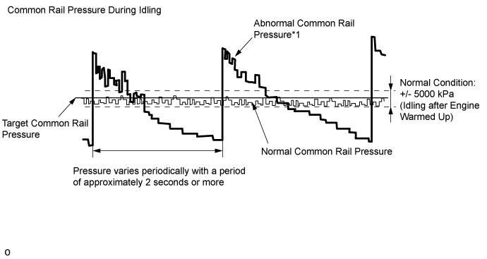
| Result | Proceed to |
| While idling the vehicle, "Common Rail Pressure" deviates from the normal range and varies periodically with a period of approximately 2 seconds or more*1 | A |
| "Common Rail Pressure" is normal while idling the vehicle, but "Fuel Press" does not follow "Target Common Rail Pressure" when the accelerator pedal is fully depressed in 2nd gear*2 | |
| Except above | B |
- NOTICE:
|
| ||||
| B | |
| 18.REPLACE FUEL SUPPLY PUMP ASSEMBLY (SUCTION CONTROL VALVE) |
Replace the fuel supply pump assembly ().
| NEXT | |
| 19.BLEED AIR FROM FUEL SYSTEM |
Bleed the air from the fuel system ().
Perform PM forced regeneration ().
- HINT:
- When fuel lines are disconnected, air may enter the fuel lines, leading to engine starting trouble. Therefore, perform forced regeneration and bleed the air from the fuel lines.
| NEXT | |
| 20.PERFORM FUEL SUPPLY PUMP INITIALIZATION |
Perform fuel supply pump initialization ().
|
| ||||
| 21.REPAIR OR REPLACE CLOGGED FUEL LINE |
Repair or replace the clogged (including frozen fuel) fuel pipe.
Replace the fuel filter element sub-assembly.
- HINT:
- If "Common Rail Pressure" does not follow "Target Common Rail Pressure" when the accelerator pedal is fully depressed in 2nd gear, replace the fuel filter element sub-assembly.
| NEXT | |
| 22.BLEED AIR FROM FUEL SYSTEM |
Bleed the air from the fuel system ().
Perform PM forced regeneration ().
- HINT:
- When fuel lines are disconnected, air may enter the fuel lines, leading to engine starting trouble. Therefore, perform forced regeneration and bleed the air from the fuel lines.
|
| ||||
| 23.INSPECT EGR VALVE ASSEMBLY |
Connect the GTS to the DLC3.
Turn the engine switch on (IG) and turn the GTS on.
Enter the following menus: Engine and ECT / Active Test / Control the EGR Step Position or Control the EGR Step Position #2.
While continuously changing the Active Test value to 0, 30, 60, 90, 60, 30 and 0%, check that Actual EGR Valve Pos or Actual EGR Valve Pos #2 smoothly changes to the set opening lift amount.
- OK:
- Value smoothly changes to within +/- 10% of set opening lift amount.
- HINT:
Next, after the engine is warmed up, stop the engine and wait for 15 seconds. After that, start the engine again and idle it for 30 seconds. Then stop the engine and wait for 15 seconds. After starting the engine again, read the Data List values while idling.
Enter the following menus: Data List / EGR Close Lrn. Val. and EGR Close Lrn. Val. #2.
Read the values.
- Standard:
- 3.5 to 4.5 V
|
| ||||
|
| ||||
| 24.REMOVE DEPOSIT (EGR VALVE ASSEMBLY) |
Remove the No. 1 and No. 2 EGR valve assembly ().
Visually check the EGR valve assembly for deposits.
If there are deposits, clean the EGR valve assembly.
- NOTICE:
- HINT:
Reinstall the EGR valve assembly ().
|
| ||||
| 25.PERFORM PILOT QUANTITY LEARNING (DETAIL) |
Perform the injector pilot quantity learning (Detail) ().
| NEXT | |
| 26.CHECK ROUGH IDLING OR EXCESSIVE ENGINE VIBRATIONS |
Check rough idling or excessive engine vibrations.
| Result | Proceed to |
| Rough idling or excessive engine vibrations do not occur | A |
| Except above | B |
|
| ||||
| B | |
| 27.CHECK AND REPLACE ENGINE MOUNTING INSULATOR |
Check the following items and repair or replace the malfunctioning part if necessary.
Check that the engine mounting insulators are installed correctly.
Check that the engine mounting insulators are not twisted.
Check that deformation of an engine mounting insulator is not causing the engine to contact the vehicle body.
| NEXT | |
| 28.CONFIRM WHETHER MALFUNCTION HAS BEEN SUCCESSFULLY REPAIRED |
| NEXT | ||
| ||