Land Cruiser URJ200 URJ202 GRJ200 VDJ200 - 1VD-FTV ENGINE CONTROL
READ OUTPUT DTC (RELATING TO ENGINE)
TAKE SNAPSHOT DURING IDLING AND 4000 RPM (PROCEDURE 2)
TAKE SNAPSHOT DURING LACK OF POWER (PROCEDURE 3)
CHECK SNAPSHOT (FUEL PRESS, TARGET COMMON RAIL PRESSURE, MAP AND TARGET BOOSTER PRESSURE)
CLEAN FUEL FILTER CASE AND REPLACE FUEL FILTER
REPLACE INJECTOR ASSEMBLIES OF ALL CYLINDERS
REGISTER INJECTOR COMPENSATION CODE AND PERFORM PILOT QUANTITY LEARNING
CONFIRM WHETHER MALFUNCTION HAS BEEN SUCCESSFULLY REPAIRED
READ VALUE USING GTS (MAP AND ATMOSPHERIC PRESSURE)
CHECK TURBOCHARGER SUB-ASSEMBLY
CHECK FOR INTERMITTENT PROBLEMS
REPLACE MANIFOLD ABSOLUTE PRESSURE SENSOR
REPAIR OR REPLACE AIR INTAKE SYSTEM
REPLACE TURBOCHARGER SUB-ASSEMBLY
CONFIRM WHETHER MALFUNCTION HAS BEEN SUCCESSFULLY REPAIRED
REPLACE FUEL SUPPLY PUMP ASSEMBLY (SUCTION CONTROL VALVE)
REPAIR OR REPLACE CLOGGED FUEL LINE
PERFORM SUPPLY PUMP INITIALIZATION
CONFIRM WHETHER MALFUNCTION HAS BEEN SUCCESSFULLY REPAIRED
PERFORM ACTIVE TEST USING GTS (ACTIVATE THE EGR VALVE CLOSE)
REMOVE DEPOSIT (EGR VALVE ASSEMBLY)
REPAIR OR REPLACE AIR INTAKE SYSTEM
CONFIRM WHETHER MALFUNCTION HAS BEEN SUCCESSFULLY REPAIRED
CHECK CLOGGED EXHAUST SYSTEM (DPF, CCo CATALYTIC CONVERTER)
INSPECT TURBOCHARGER SUB-ASSEMBLY
CHECK FOR INTERMITTENT PROBLEMS
REPLACE CLOGGED PARTS (DPF, CCo CATALYTIC CONVERTER)
REPLACE TURBOCHARGER SUB-ASSEMBLY
CONFIRM WHETHER MALFUNCTION HAS BEEN SUCCESSFULLY REPAIRED
COMPARE WITH SIMILAR VEHICLE WITH SAME ENGINE
EXPLAIN THE INVESTIGATION RESULT TO CUSTOMER
ECD SYSTEM (w/ DPF) - Lack of Power or Hesitation
DESCRIPTION
| Malfunction Condition | Main Trouble Area | Related Trouble Area |
Lack of power caused by abnormal fuel injection volume (fuel supply pump assembly malfunction, injector assembly malfunction, etc.) Lack of power caused by intake air volume shortage (turbocharger malfunction, or front exhaust pipe or exhaust manifold converter blocked) | (a) Injector assembly malfunctions Injector sliding malfunction Injector stuck closed Injector stuck open Deposits in injector Injector circuit malfunction Suction control valve (fuel supply pump assembly) Intake air system leakage or clogged Turbocharger sub-assembly Front exhaust pipe blockage Exhaust manifold converter blockage EGR valve does not close Throttle valve does not open | Pressure discharge valve (common rail assembly (for bank 2)) (P1271 stored simultaneously) Intake air system blockage EGR system Fuel filter element sub-assembly is clogged Throttle valve Mass air flow meter Compression pressure Injector compensation code Fuel leak Glow plug Fuel pressure sensor (common rail assembly (for bank 1)) Manifold absolute pressure sensor Vacuum hose connection for manifold absolute pressure sensor Injector driver (P062D or P062E stored simultaneously) Vehicle modifications Clutch disc wear Low quality fuel Frozen fuel ECM |
- HINT:
| Faults and Symptoms of Common Rail Diesel Components |
Engine Control
| Main fault | Decrease in performance (foreign matter is stuck) |
| Symptoms | Lack of power, black smoke |
| Data List | MAF |
| |
| Symptom and Corresponding Main Fault | Lack of power (no black smoke) due to air filter blockage or crushed or leaking air duct Black smoke (no lack of power) due to leakage between the turbo and intake manifold |
| Data List | MAP Target Booster Pressure When the accelerator is fully depressed, if MAP is 20 kPa lower than Target Booster Pressure for more than 5 seconds, then a lack of power will be felt. MAF |
| Main fault | Air leak in the turbocharged air passage Turbocharger sub-assembly (turbine, bearing, variable nozzle) |
| Symptoms | Lack of power (when vehicle is starting, under heavy load) (Black smoke is not emitted when racing while vehicle is stopped) |
| Data List | MAP, Target Booster Pressure When the accelerator is fully depressed, if MAP is 20 kPa lower than Target Booster Pressure for more than 5 seconds, then a lack of power will be felt. With the engine switch on (IG) or during idling, MAP = atmospheric pressure (standard atmospheric pressure = 101 kPa). When the engine speed is about 1500 rpm or more, the turbocharger starts to take effect and MAP becomes higher than atmospheric pressure. Atmospheric pressure decreases by 1 kPa each time elevation increases by 100 m, and is also affected by the current weather conditions. |
| Main fault | Blockage |
| Symptoms | Lack of power (high engine speed, under heavy load) |
| Data List | MAP, Target Booster Pressure When the accelerator is fully depressed, if MAP is 20 kPa lower than Target Booster Pressure for more than 5 seconds, then a lack of power will be felt. |
| Main fault | Glow system malfunction |
| Symptoms | Difficult to start, rough idle, knocking, white smoke (when cold) |
| Data List | Check the glow plug indicator light |
| Diagnostic Point | Measure the resistance of the glow plug |
| Main fault | Damaged, seized up |
| Symptoms | Cannot crank, crank speed is low, strange noise |
| Main fault | Loss of compression |
| Symptoms | Rough idle (lack of power always) |
| Data List | Engine Speed of Cyl# When cranking during the "Check the Cylinder Compression" Active Test, if there is a high speed cylinder, approx. 100 rpm more than the other cylinders, that cylinder may lose compression. When an Injector Feedback Val is more than 3 mm3/st, there may be a malfunction in the corresponding cylinder. |
Diesel Injection
| Main fault | - |
| Symptoms | Difficult to start, engine stalling, rough idle, lack of power |
| Data List | Common Rail Pressure, Target Common Rail Pressure, Target Pump SCV Current Common Rail Pressure is within 5000 kPa of Target Common Rail Pressure during idling with the engine warmed up (engine coolant temperature is higher than 70°C (158°F)). If the fuel pressure is 20000 kPa below the target common rail pressure, then a lack of power will be felt. If the fuel pressure is below 25000 kPa, then idling will be rough. If Target Pump SCV Current is 3000 mA or higher, the suction control valve may be stuck.
The fuel pressure changes at engine start, but is approx. 25000 kPa at engine start after the engine is warmed up. When Target Pump SCV Current is 3000 mA or higher, the suction control valve has a tendency to become stuck. |
| Diagnostic Trouble Code | Even if Common Rail Pressure is below Target Common Rail Pressure, a DTC will not be stored. |
| Main fault | Blockage |
| Symptoms | Difficult to start, engine stalling, rough idle, lack of power |
| Data List | Common Rail Pressure, Target Common Rail Pressure Common Rail Pressure is within 5000 kPa of Target Common Rail Pressure during idling with the engine warmed up (engine coolant temperature is higher than 70°C (158°F)). If the fuel pressure is 20000 kPa below the target pressure, then a lack of power will be felt. If the fuel pressure is below 25000 kPa, then idling will be rough.
|
| Diagnostic Trouble Code | Even if Common Rail Pressure is below Target Common Rail Pressure, a DTC will not be stored. |
| Main fault | Blockage |
| Symptoms | Rough idle, lack of power, black smoke, white smoke, knocking |
| Data List | Injection Feedback Val When an Injector Feedback Val is more than 3 mm3/st, there may be a malfunction in the corresponding cylinder. This value can be read after idling for 1 minute. |
| Main fault | Circuit fault: The injector assembly does not open. |
| Symptoms | Difficult to start, rough idle, lack of power, black smoke, white smoke, knocking |
| Data List | Same as injector assembly |
| Diagnostic Trouble Code | When the injector driver has a fault, some DTCs may be stored. |
| Main fault | Open circuit, decrease in performance (foreign matter is stuck) |
| Symptoms | Difficult to start, rough idle, engine stall, lack of power |
| Data List | Common Rail Pressure, Target Common Rail Pressure Common Rail Pressure is within 5000 kPa of Target Common Rail Pressure during idling with the engine warmed up (engine coolant temperature is higher than 70°C (158°F)). |
| Diagnostic Code | When the fuel pressure sensor has a fault, some DTCs may be stored. |
| Main fault | - |
| Symptoms | Difficult to start, rough idle (especially when cold) |
Diesel EGR
| Main fault | Does not move smoothly Does not close fully |
| Symptoms | Rough Idle EGR valve stuck closed: A loud turbocharger sound. EGR valve stuck open: Difficult to start (does not stall), black smoke, white smoke (when engine is cold), lack of power, jerking (If there is an excess in the quantity of EGR and there is a heavy load, when the vehicle starts moving, a lack of power will be felt. Also, when racing the engine, there will be some black smoke). |
| Data List | Actual EGR Valve Pos, Actual EGR Valve Pos #2, Target EGR Valve Pos, Target EGR Valve Pos #2 Generally, Actual EGR Valve Pos = Target EGR Valve Pos +/-5% (fully closed: 0%, fully open: 100%). Using the EGR valve Active Test, check whether Actual EGR Valve Pos follows Target EGR Valve Pos (the engine coolant temperature and intake air temperature should be considered when a malfunction occurs). EGR valve is fully closed when the engine switch is on (IG) (engine stopped). EGR valve opens to the halfway point at idling after the engine is warmed up. When the EGR valve does not close, MAF (Mass Air Flow) decreases when the vehicle is accelerated at full throttle. MAP also decreases in comparison to Target Booster Pressure. However, there is not a large difference. When leaving the vehicle idling, the normal range of EGR Close Lrn. Val. is 3.5 to 4.5 V. In cases when EGR Close Lrn. Val. is out of the normal range (3.5 to 4.5 V), it is possible that the EGR valve cannot completely close. |
Diesel Throttle
| Main fault | Stuck, does not move smoothly |
| Symptoms | Stuck closed: Lack of power, difficult to start, rough idle, engine stall, black smoke. These may occur when stuck almost fully closed. Stuck open: Turbocharger sound increases. When the engine is stopped, engine vibrations may occur. |
| Data List | Actual Throttle Position, Actual Throttle Position #2 Fully closed: 0% Fully open: 100% When the engine switch is on (IG) (engine stopped), the diesel throttle is fully open. When idling, the diesel throttle is at the halfway point. When the engine switch is turned from on (IG) to off, the throttle is fully closed temporarily. |
| Data List Related to Lack of Power |
INSPECTION PROCEDURE
| Explanation of Symptom |
| Lack of Power | The power of the diesel engine is determined by the quantity of injected fuel and the quantity of intake air. The quantity of injected fuel is determined by the fuel pressure and the amount of time the injector assembly is open. Basically, the fuel pressure is controlled so that it reaches the target fuel pressure. The throttle valve does not restrict air flow volume, so the manifold absolute pressure is almost the same as atmospheric pressure when idling. At more than approximately 1500 rpm, the turbo starts to operate causing the manifold absolute pressure to become higher than atmospheric pressure. The manifold absolute pressure is controlled so that it reaches the Target Booster Pressure when accelerating the vehicle at full throttle. Also, when accelerating the vehicle at full throttle, the throttle is fully open and the EGR valve is fully closed, preserving the mass air flow. |
- NOTICE:
| 1.READ OUTPUT DTC (RELATING TO ENGINE) |
Connect the GTS to the DLC3.
Turn the engine switch on (IG) and turn the GTS on.
Enter the following menus: Engine and ECT / Trouble Codes.
Read the pending DTCs.
| Result | Proceed to |
| No DTCs are output | A |
| Engine related DTCs are output | B |
- HINT:
- If only DTC P1608 is output, proceed to step 2.
|
| ||||
| A | |
| 2.TAKE SNAPSHOT DURING IDLING AND 4000 RPM (PROCEDURE 2) |
Connect the GTS to the DLC3.
Start the engine and turn the GTS on.
Enter the following menus: Engine and ECT / Data List / Lack of power.
With no load after the engine is warmed up, take a snapshot when idling and at 4000 rpm.
- HINT:
| NEXT | |
| 3.TAKE SNAPSHOT DURING LACK OF POWER (PROCEDURE 3) |
Connect the GTS to the DLC3.
Start the engine and turn the GTS on.
Enter the following menus: Engine and ECT / Data List / All Data.
Check for a lack of power during the driving test.
- HINT:
| Result | Proceed to |
| Apparent lack of power is present | A |
| Apparent lack of power is not present | B |
|
| ||||
| A | |
| 4.CHECK SNAPSHOT (MAP AND MAF) |
Check MAP and MAF in the snapshot taken in procedure 2 when the engine was running at 4000 rpm with no load.
| Result | Proceed to |
| MAP is 105 kPa or higher and MAF is 84 gm/sec or more*1 | A |
| MAP is below 90 kPa*2 | B |
| Except above*3 | C |
- HINT:
- The above values were measured under standard atmospheric pressure. The values are influenced by elevation, weather conditions, etc.
- Standard atmospheric pressure is 101 kPa. For every 100 m increase in elevation, pressure drops by 1 kPa. This varies by weather.
- *1: There may be a problem in the fuel injection system or intake system.
- *2: There may be a problem in the turbocharger system.
- *3: There may be a problem in the intake system or a problem with the EGR valve (valve stuck open or valve does not close).
|
| ||||
|
| ||||
| A | |
| 5.CHECK SNAPSHOT (FUEL PRESS, TARGET COMMON RAIL PRESSURE, MAP AND TARGET BOOSTER PRESSURE) |
Check Common Rail Pressure, Target Common Rail Pressure, MAP and Target Booster Pressure in the snapshot taken in procedure 3 when the vehicle was accelerating with the accelerator pedal fully depressed in 2nd gear.
| Result | Proceed to |
| MAP is below 190 kPa at an engine speed of 3000 rpm | A |
| Difference between Common Rail Pressure and Target Common Rail Pressure is 20000 kPa or more | B |
| Except above | C |
- HINT:
Standard atmospheric pressure is 101 kPa. For every 100 m increase in elevation, pressure drops by 1 kPa. This varies by weather.
When the accelerator pedal is fully depressed and the engine speed is 3000 rpm, the MAP should be higher than 195 kPa.
|
| ||||
|
| ||||
| A | |
| 6.CHECK INTAKE SYSTEM |
Check for air leaks and blockages between the air cleaner case and turbocharger, and between the turbocharger and intake manifold.
- HINT:
- OK:
- No leakage or blockage.
|
| ||||
| OK | |
| 7.CLEAN FUEL FILTER CASE AND REPLACE FUEL FILTER |
Clean the fuel filter case and replace the fuel filter.
- HINT:
- Be sure to clean the inside of the fuel filter case as the fuel injectors may not operate properly if the fuel filter is installed with foreign matter remaining inside the fuel filter case.
| NEXT | |
| 8.REPLACE INJECTOR ASSEMBLIES OF ALL CYLINDERS |
Replace the injector assemblies ().
- NOTICE:
| NEXT | |
| 9.BLEED AIR FROM FUEL SYSTEM |
Bleed the air from the fuel system ().
Perform PM forced regeneration ().
- HINT:
- When fuel lines are disconnected, air may enter the fuel lines, leading to engine starting trouble. Therefore, perform forced regeneration and bleed the air from the fuel lines.
| NEXT | |
| 10.REGISTER INJECTOR COMPENSATION CODE AND PERFORM PILOT QUANTITY LEARNING |
Register the injector compensation code ().
Perform the injector pilot quantity learning ().
| NEXT | |
| 11.CONFIRM WHETHER MALFUNCTION HAS BEEN SUCCESSFULLY REPAIRED |
| NEXT | ||
| ||
| 12.READ VALUE USING GTS (MAP AND ATMOSPHERIC PRESSURE) |
Connect the GTS to the DLC3.
Turn the engine switch on (IG) and turn the GTS on.
Enter the following menus: Engine and ECT / Data List / MAP and Atmosphere Pressure.
Compare MAP to Atmosphere Pressure when the engine switch is on (IG) (do not start the engine).
- Standard:
- Difference between MAP and Atmosphere Pressure is less than 8 kPa.
- HINT:
| Result | Proceed to |
| MAP and Atmosphere Pressure have same value | A |
| MAP is different from actual atmospheric pressure | B |
| Atmosphere Pressure is different from actual atmospheric pressure | C |
|
| ||||
|
| ||||
| A | |
| 13.CHECK AIR INTAKE SYSTEM |
Check for air leaks and blockages between the air cleaner case and turbocharger, and between the turbocharger and intake manifold.
| Result | Proceed to |
| Leaks and/or blockages exist in the intake system | A |
| No leaks or blockages in the intake system | B |
- HINT:
|
| ||||
| B | |
| 14.CHECK TURBOCHARGER SUB-ASSEMBLY |
Check the turbocharger sub-assembly (for bank 1 or bank 2) ().
|
| ||||
| OK | |
| 15.CHECK FOR INTERMITTENT PROBLEMS |
Check for intermittent problems ().
|
| ||||
| 16.REPLACE MANIFOLD ABSOLUTE PRESSURE SENSOR |
Replace the manifold absolute pressure sensor.
|
| ||||
| 17.REPLACE ECM |
Replace the ECM ().
|
| ||||
| 18.REPAIR OR REPLACE AIR INTAKE SYSTEM |
Repair or replace the malfunctioning part in the air intake system.
|
| ||||
| 19.REPLACE TURBOCHARGER SUB-ASSEMBLY |
Replace the turbocharger sub-assembly ().
| NEXT | |
| 20.CONFIRM WHETHER MALFUNCTION HAS BEEN SUCCESSFULLY REPAIRED |
| NEXT | ||
| ||
| 21.INSPECT CLOGGED FUEL PIPE |
Connect the GTS to the DLC3.
Start the engine and turn the GTS on.
Enter the following menus: Engine and ECT / Data List / Diesel Injection.
With no load after the engine is warmed up, take a snapshot when idling and when the vehicle is accelerating with the accelerator pedal fully depressed in 2nd gear.
Check the Target Common Rail Pressure and Common Rail Pressure value.
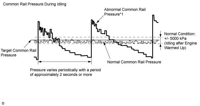
| Result | Proceed to |
| While idling the vehicle, "Common Rail Pressure" deviates from the normal range and varies periodically with a period of approximately 2 seconds or more*1 | A |
| "Common Rail Pressure" is normal while idling the vehicle, but "Common Rail Pressure" does not follow "Target Common Rail Pressure" when the accelerator pedal is fully depressed in 2nd gear*2 | |
| Except above | B |
- NOTICE:
|
| ||||
| B | |
| 22.REPLACE FUEL SUPPLY PUMP ASSEMBLY (SUCTION CONTROL VALVE) |
Replace the fuel supply pump assembly ().
|
| ||||
| 23.REPAIR OR REPLACE CLOGGED FUEL LINE |
Repair or replace the clogged (including frozen fuel) fuel pipe.
Replace the fuel filter element sub-assembly.
- HINT:
- If "Common Rail Pressure" does not follow "Target Common Rail Pressure" when the accelerator pedal is fully depressed in 2nd gear, replace the fuel filter element sub-assembly.
| NEXT | |
| 24.BLEED AIR FROM FUEL SYSTEM |
Bleed the air from the fuel system ().
Perform PM forced regeneration ().
- HINT:
- When fuel lines are disconnected, air may enter the fuel lines, leading to engine starting trouble. Therefore, perform forced regeneration and bleed the air from the fuel lines.
| NEXT | |
| 25.PERFORM SUPPLY PUMP INITIALIZATION |
Perform supply pump initialization ().
| NEXT | |
| 26.CONFIRM WHETHER MALFUNCTION HAS BEEN SUCCESSFULLY REPAIRED |
Connect the GTS to the DLC3.
Start the engine and turn the GTS on.
Enter the following menus: Engine and ECT / Active Test / Test the Fuel Leak / Data List / Common Rail Pressure, Target Common Rail Pressure.
Take a snapshot with the GTS during the Active Test.
Measure the difference between the target fuel pressure (Target Common Rail Pressure) and the actual fuel pressure (Common Rail Pressure) when the "Test the Fuel Leak" Active Test is performed.
- HINT:
- In order to obtain an exact measurement, perform the Active Test 5 times and measure the difference once each time the Active Test is performed.
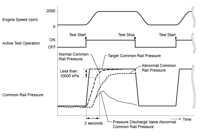
- OK:
- The difference between the target fuel pressure and the actual fuel pressure 2 seconds after the Active Test starts is less than 10000 kPa.
- HINT:
| NEXT | ||
| ||
| 27.CHECK AIR INTAKE SYSTEM |
Check for air leaks and blockages between the air cleaner case and turbocharger, and between the turbocharger and intake manifold.
| Result | Proceed to |
| No leaks or blockages in the intake system | A |
| Leaks and/or blockages exist in the intake system | B |
- HINT:
|
| ||||
| A | |
| 28.INSPECT EGR VALVE ASSEMBLY |
Connect the GTS to the DLC3.
Turn the engine switch on (IG) and turn the GTS on.
Enter the following menus: Engine and ECT / Active Test / Control the EGR Step Position or Control the EGR Step Position #2.
While continuously changing the Active Test value to 0, 30, 60, 90, 60, 30 and 0%, check that Actual EGR Valve Pos or Actual EGR Valve Pos #2 smoothly changes to the set opening lift amount.
- OK:
- Value smoothly changes to within +/- 10% of set opening lift amount.
- HINT:
Next, after the engine is warmed up, stop the engine and wait for 15 seconds. After that, start the engine again and idle it for 30 seconds. Then stop the engine and wait for 15 seconds. After starting the engine again, read the Data List values while idling.
Enter the following menus: Data List / EGR Close Lrn. Val. or EGR Close Lrn. Val. #2.
Read the values.
- Standard:
- 3.5 to 4.5 V
|
| ||||
| OK | |
| 29.PERFORM ACTIVE TEST USING GTS (ACTIVATE THE EGR VALVE CLOSE) |
Connect the GTS to the DLC3.
Start the engine and warm it up, and make sure the A/C switch and all accessory switches are off.
Turn the engine switch off. Wait for 30 seconds, and then restart the engine.
Turn the GTS on.
Enter the following menus: Powertrain / Engine and ECT / Data List / MAF.
Read the MAF value displayed on the GTS while the engine is idling.
Enter the following menus: Engine and ECT / Active Test / Activate the EGR Valve Close.
Read the MAF value when the EGR valve is closed using the Active Test function.
- HINT:
| Active Test | Result | Proceed to |
| Activate the EGR Valve Close: Off (Open) to On (Closed) | MAF value does not change | A |
| MAF value changes | B |
- NOTICE:
- As the measured values may differ from those shown below due to factors such as differences in measuring environments and changes in vehicle condition due to aging, do not use these values to determine whether the vehicle is malfunctioning or not.
- HINT:
- The problem may be a temporary one, due to the entry of deposits or foreign matter. Check that there are no deposits or foreign matter in the EGR valve assembly or mass air flow meter.
- Reference:
EGR Valve Condition (Opening) Measuring Condition MAF (Reference) Open (40%) Atmosphere pressure: 101 kPaIntake air temperature: 30°C (86°F)Engine coolant temperature: 88°C (190°F)3 to 10 gm/sec Closed (0%) 14 to 23 gm/sec
|
| ||||
| A | |
| 30.READ VALUE USING GTS (MAF) |
Connect the GTS to the DLC3.
Turn the engine switch on (IG) and turn the GTS on.
Enter the following menus: Engine and ECT / Data List / MAF.
Read the value.
- Standard:
GTS Display Condition Specified Condition MAF Engine not running Less than 0.5 gm/sec
|
| ||||
| OK | |
| 31.REMOVE DEPOSIT (EGR VALVE ASSEMBLY) |
Remove the No. 1 and No. 2 EGR valve assembly ().
Visually check the EGR valve assembly for deposits.
If there are deposits, clean the EGR valve assembly.
- NOTICE:
- HINT:
Reinstall the EGR valve assembly ().
|
| ||||
| 32.REPAIR OR REPLACE AIR INTAKE SYSTEM |
Repair or replace the malfunctioning part in the air intake system.
|
| ||||
| 33.REPLACE MASS AIR FLOW METER |
Replace the mass air flow meter ().
- HINT:
|
| ||||
| 34.REPLACE EGR COOLER |
Replace the EGR cooler ().
| NEXT | |
| 35.CONFIRM WHETHER MALFUNCTION HAS BEEN SUCCESSFULLY REPAIRED |
|
| ||||
| OK | ||
| ||
| Go to step 45 |
| 36.CHECK CLOGGED EXHAUST SYSTEM (DPF, CCo CATALYTIC CONVERTER) |
Remove the front exhaust pipe assembly (for bank 1 DPF catalytic converter) ().
Remove the front No. 2 exhaust pipe assembly (for bank 2 DPF catalytic converter) ().
Remove the monolithic converter assembly RH (for bank 1 CCo catalytic converter) ().
Remove the monolithic converter assembly LH (for bank 2 CCo catalytic converter) ().
Visually check for catalyst clogging or carbon deposits adhering to the inner wall of the exhaust pipe upstream of the catalyst.
- OK:
- Less than 10% of the cells are clogged.
Reinstall the front exhaust pipe assembly (for bank 1 DPF catalytic converter) ().
Reinstall the front No. 2 exhaust pipe assembly (for bank 2 DPF catalytic converter) ().
Reinstall the monolithic converter assembly RH (for bank 1 CCo catalytic converter) ().
Reinstall the monolithic converter assembly LH (for bank 2 CCo catalytic converter) ().
|
| ||||
| OK | |
| 37.INSPECT TURBOCHARGER SUB-ASSEMBLY |
Inspect the turbocharger sub-assembly (for bank 1 or bank 2) ().
|
| ||||
| OK | |
| 38.CHECK FOR INTERMITTENT PROBLEMS |
Check for intermittent problems ().
|
| ||||
| 39.REPLACE EGR COOLER |
Replace the EGR cooler ().
|
| ||||
| 40.REPLACE CLOGGED PARTS (DPF, CCo CATALYTIC CONVERTER) |
- HINT:
- Replace the DPF catalytic converter for bank 1 and bank 2 at the same time.
Replace the front exhaust pipe assembly) (for bank 1 DPF catalytic converter ().
Replace the front No. 2 exhaust pipe assembly (for bank 2 DPF catalytic converter) ().
Replace the monolithic converter assembly RH (for bank 1 CCo catalytic converter) ().
Replace the monolithic converter assembly LH (for bank 2 CCo catalytic converter) ().
| NEXT | |
| 41.CATALYST RECORD CLEAR |
Perform the catalyst record clear ().
|
| ||||
| 42.REPLACE TURBOCHARGER SUB-ASSEMBLY |
Replace the turbocharger sub-assembly (for bank 1) ().
Replace the turbocharger sub-assembly (for bank 2) ().
| NEXT | |
| 43.CONFIRM WHETHER MALFUNCTION HAS BEEN SUCCESSFULLY REPAIRED |
| NEXT | ||
| ||
| 44.COMPARE WITH SIMILAR VEHICLE WITH SAME ENGINE |
Confirm the situation in which the lack of power was experienced by the customer again, and compare the driving feeling under the same conditions using a similar vehicle with the same engine while collecting data with the GTS.
- HINT:
- Confirm the state of the following conditions when the lack of power was experienced.
| Result | Proceed to |
| Significant difference is found | A |
| Significant difference is not found | B |
|
| ||||
| B | |
| 45.EXPLAIN THE INVESTIGATION RESULT TO CUSTOMER |
Vehicle performance is normal.
There is no problem at this point in time. However, if the problem reoccurs, ask the customer to explain in detail the situation in which the problem occurred.
The best course may be to have the customer ride in another vehicle with the same specifications to understand that there is no problem with the customer's vehicle.
| NEXT | ||
| ||