Land Cruiser URJ200 URJ202 GRJ200 VDJ200 - 1VD-FTV ENGINE CONTROL
CHECK OTHER DTC OUTPUT (IN ADDITION TO DTC P2453 OR P245F)
CHECK CONNECTION OF VACUUM HOSE (DIFFERENTIAL PRESSURE SENSOR - VACUUM TRANSMITTING PIPE)
CHECK BLOCKAGE OF VACUUM HOSE AND TRANSMITTING PIPE
READ VALUE USING GTS (DPF DIFFERENTIAL PRESSURE AND DPF DIFFERENTIAL PRESSURE #2)
REPLACE DIFFERENTIAL PRESSURE SENSOR ASSEMBLY
CONFIRM WHETHER MALFUNCTION HAS BEEN SUCCESSFULLY REPAIRED
DTC P2453 Diesel Particulate Filter Pressure Sensor "A" Circuit Range/Performance
DTC P245F Diesel Particulate Filter Pressure Sensor "B" Circuit Range/Performance
DESCRIPTION
- HINT:
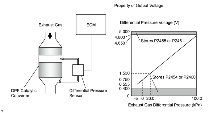
The two sensing chambers of the differential pressure sensor assembly are mounted to monitor the pressure before and after the DPF catalytic converter. The sensor itself is not located on the engine assembly in order to reduce the influence of vibration. The sensor is a semiconductor-type that is not influenced by exhaust gases.
The ECM compares the exhaust gas pressure before and after the DPF catalytic converter by monitoring the pressure using the upstream and downstream sensing chambers of the differential pressure sensor assembly. If the difference between the pressure before and after the catalytic converter exceeds a predetermined level, the ECM judges that the catalytic converter is clogged with particulate matter (PM). When the ECM judges that a partially clogged condition exists, the ECM begins to perform PM forced regeneration.
- HINT:
- If the vacuum hoses of the differential pressure sensor assembly are incorrectly connected (crossed), the ECM interprets this as an abnormal pressure difference, DTC P2453 or P245F is stored and the MIL illuminates.
| DTC Detection Drive Pattern | DTC Detection Condition | Trouble Area |
| Engine is running at 4000 rpm with no load for 10 seconds or more. | The output voltage from the differential pressure sensor assembly indicates a reversal of positive and negative pressure. (1 trip detection logic) | Incorrect differential pressure sensor assembly hose routing Differential pressure sensor assembly vacuum hose is clogged Blockage in vacuum transmitting pipe sub-assembly Differential pressure sensor assembly ECM |
| DTC No. | Data List |
| P2453 | DPF Differential Pressure |
| P245F | DPF Differential Pressure #2 |
- HINT:
| Condition | Differential Pressure Output | Sensor Condition |
| Engine switch on (IG) | Approximately 0 kPa | Normal |
| Always | -5 kPa or less or higher than 99 kPa | Open or short circuit |
| 4000 rpm (No engine load) | Negative output | Incorrect hose routing |
MONITOR DESCRIPTION
In order to detect abnormality in the differential pressure sensor assembly, the ECM always monitors the output voltage from the sensor. When the sensor output voltage is a reversal of positive and negative pressure, the ECM interprets this as an incorrect vacuum hose arrangement of the sensor, or determines that the vacuum hoses are clogged, and illuminates the MIL.
INSPECTION PROCEDURE
- NOTICE:
- HINT:
- Read freeze frame data using the GTS. Freeze frame data records the engine condition when malfunctions are detected. When troubleshooting, freeze frame data can help determine if the vehicle was moving or stationary, if the engine was warmed up or not, and other data from the time the malfunction occurred.
| 1.CHECK OTHER DTC OUTPUT (IN ADDITION TO DTC P2453 OR P245F) |
Connect the GTS to the DLC3.
Turn the engine switch on (IG) and turn the GTS on.
Enter the following menus: Engine and ECT / Trouble Codes.
Read the DTCs.
| Result | Proceed to |
| P2453 or P245F is output | A |
| P2453 or P245F and other DTCs are output | B |
- HINT:
- If codes other than P2453 or P245F are output, perform troubleshooting for those DTCs first.
|
| ||||
| A | |
| 2.CHECK CONNECTION OF VACUUM HOSE (DIFFERENTIAL PRESSURE SENSOR - VACUUM TRANSMITTING PIPE) |
Check if the vacuum hose routing between the differential pressure sensor assembly and vacuum transmitting pipe is correct ().
Check that there is no exhaust gas leakage between the differential pressure sensor assembly and vacuum transmitting pipe.
|
| ||||
| OK | |
| 3.CHECK BLOCKAGE OF VACUUM HOSE AND TRANSMITTING PIPE |
- CAUTION:
- Be careful of being burned by exhaust gases during the following inspection.
Disconnect the vacuum hoses (both upstream and downstream) from the differential pressure sensor assembly.
Start the engine.
Check if there are exhaust gas pulsations from both vacuum hoses during idling.
- OK:
- Exhaust gas pulsation exists.
|
| ||||
| OK | |
| 4.READ VALUE USING GTS (DPF DIFFERENTIAL PRESSURE AND DPF DIFFERENTIAL PRESSURE #2) |
Connect the GTS to the DLC3.
Turn the engine switch on (IG) and turn the GTS on.
Enter the following menus: Powertrain / Engine and ECT / Data List / DPF Differential Pressure and DPF Differential Pressure #2.
Check that the differential pressure is as specified below.
| Condition | Differential Pressure Output | Sensor Condition |
| Engine switch on (IG) | Approximately 0 kPa | Normal |
|
| ||||
|
| ||||
| 5.CORRECT TO NORMAL CONNECTION |
|
| ||||
| 6.REPLACE CLOGGED PARTS |
|
| ||||
| 7.REPLACE DIFFERENTIAL PRESSURE SENSOR ASSEMBLY |
When DTC P2453 is output:
When DTC P245F is output:
| NEXT | |
| 8.CONFIRM WHETHER MALFUNCTION HAS BEEN SUCCESSFULLY REPAIRED |
Connect the GTS to the DLC3.
Turn the engine switch on (IG) and turn the GTS on.
Clear the DTCs ().
Turn the engine off for 30 seconds or more.
Turn the engine switch on (IG) and turn the GTS on.
Enter the following menus: Powertrain / Engine and ECT / Data List / DPF Differential Pressure and DPF Differential Pressure #2.
Check that the differential pressure is as specified below.
- HINT:
| Condition | DPF Differential Pressure DPF Differential Pressure #2 |
| 4000 rpm without load after warming up engine | 0.2 kPa or more |
Start the engine.
Engine is running at 4000 rpm with no load for 10 seconds or more.
Confirm that the DTC is not output again.
- HINT:
- Perform the following procedure using the GTS to determine whether or not the DTC judgment has been carried out.
Enter the following menus: Engine and ECT / Utility / All Readiness.
Input DTC P2453 or P245F.
Check that STATUS is NORMAL. If STATUS is INCOMPLETE or N/A, run the engine at 4000 rpm with no load for 10 seconds or more.
| NEXT | ||
| ||