Land Cruiser URJ200 URJ202 GRJ200 VDJ200 - 1VD-FTV ENGINE CONTROL
READ OUTPUT DTC (RECORD STORED DTC AND FREEZE FRAME DATA)
CHECK ANY OTHER DTCS OUTPUT (IN ADDITION TO DTC P244C, P244E, P2458 AND P2463)
CHECK FOR WHITE SMOKE (DURING PM FORCED REGENERATION)
REPLACE EXHAUST PIPE ASSEMBLIES (DPF CATALYTIC CONVERTERS)
CHECK AFTER TREATMENT CONTROL SYSTEM
REPAIR OR REPLACE MALFUNCTIONING PARTS
CONFIRM WHETHER MALFUNCTION HAS BEEN SUCCESSFULLY REPAIRED
DTC P244C Exhaust Temperature Too Low for Particulate Filter Regeneration Bank 1
DTC P244E Exhaust Temperature Too Low for Particulate Filter Regeneration Bank 2
DTC P2458 Diesel Particulate Filter Regeneration Duration
DTC P2463 Diesel Particulate Filter Restriction - Soot Accumulation
DESCRIPTION
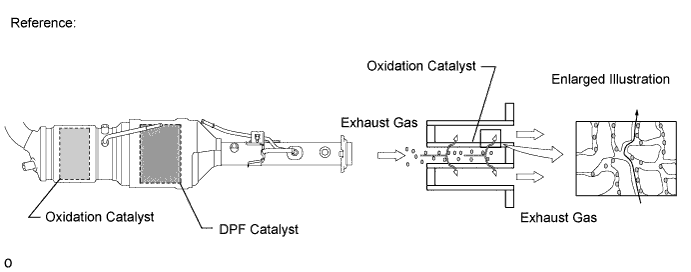
The DPF (Diesel Particulate Filter) is an emission control system which processes the particulate matter (PM) that is emitted from a diesel engine. The DPF catalyst converter has a porous ceramic structure which has a PM collecting function. The PM that is collected is continuously treated by oxidation due to catalytic action at high temperatures. However, however PM accumulation increases at low catalyst temperatures because the oxidation process slows down. The ECM performs PM forced regeneration so that the amount of accumulated PM does not exceed the threshold.
| DTC Detection Drive Pattern | DTC Detection Condition | Trouble Area |
| PM forced regeneration | During PM forced regeneration, catalyst temperature does not increase sufficiently for 3 minutes. (1 trip detection logic) | Monolithic converter assembly RH (for bank 1 CCo catalytic converter) Monolithic converter assembly LH (for bank 2 CCo catalytic converter) Front exhaust pipe assembly (for bank 1 DPF catalytic converter) Front No. 2 exhaust pipe assembly (for bank 2 DPF catalytic converter) Exhaust fuel addition injector assembly No. 2 exhaust gas temperature sensor (B1S2) No. 3 exhaust gas temperature sensor (B2S2) No. 4 exhaust gas temperature sensor (B1S3, B2S3) Fuel injection system Intake/exhaust system After treatment control system |
| DTC Detection Drive Pattern | DTC Detection Condition | Trouble Area |
| PM forced regeneration | When PM forced regeneration is manually performed, PM forced regeneration does not finish even after 60 minutes or more elapse. (1 trip detection logic) | Monolithic converter assembly RH (for bank 1 CCo catalytic converter) Monolithic converter assembly LH (for bank 2 CCo catalytic converter) Front exhaust pipe assembly (for bank 1 DPF catalytic converter) Front No. 2 exhaust pipe assembly (for bank 2 DPF catalytic converter) Exhaust fuel addition injector assembly No. 2 exhaust gas temperature sensor (B1S2) No. 3 exhaust gas temperature sensor (B2S2) No. 4 exhaust gas temperature sensor (B1S3, B2S3) Fuel injection system Intake/exhaust system After treatment control system |
| DTC Detection Drive Pattern | DTC Detection Condition | Trouble Area |
| PM forced regeneration | While driving, PM accumulation amount exceeds the limit. (1 trip detection logic) | Monolithic converter assembly RH (for bank 1 CCo catalytic converter) Monolithic converter assembly LH (for bank 2 CCo catalytic converter) Front exhaust pipe assembly (for bank 1 DPF catalytic converter) Front No. 2 exhaust pipe assembly (for bank 2 DPF catalytic converter) Exhaust fuel addition injector assembly No. 2 exhaust gas temperature sensor (B1S2) No. 3 exhaust gas temperature sensor (B2S2) No. 4 exhaust gas temperature sensor (B1S3, B2S3) Differential pressure sensor assembly Fuel injection system Intake/exhaust system After treatment control system |
- HINT:
- PM forced regeneration may be prohibited due to a fail-safe operation that is performed when another DTC is stored (including engine output limitation).
| DTC No. | Data List |
| P244C P244E P2458 P2463 | Exhaust Fuel Addition FB Exhaust Fuel Addition FB #2 Catalyst Differential Press Catalyst Differential Press #2 |
MONITOR DESCRIPTION
The ECM monitors the differential pressure between the upstream and downstream of the DPF catalyst converter and also monitors exhaust gas temperature to detect a malfunction in the DPF catalyst converter.
The ECM monitors the PM Accumulation Ratio and when the accumulated PM volume in the DPF catalyst converter exceeds the limit, the ECM illuminates the MIL.
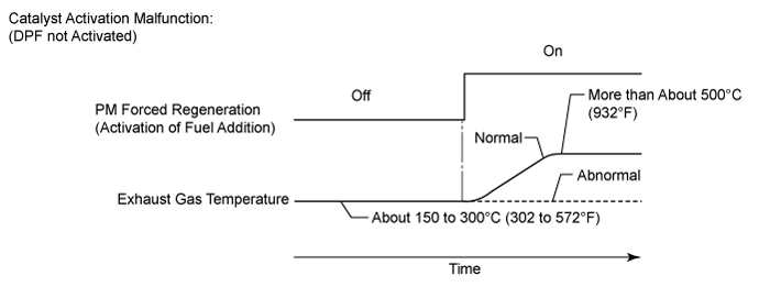
The ECM monitors exhaust gas temperature increase while the exhaust fuel addition injector assemblies adds fuel during PM forced regeneration. Exhaust gas temperature increases up to approximately 300 to 500°C (572 to 932°F) during PM forced regeneration. If the temperature does not increase even after a certain amount of time has elapsed, the ECM determines that the DPF catalyst converter is abnormal and illuminates the MIL.
When PM forced regeneration is manually performed and PM forced generation does not finish even after 60 minutes or more elapse, the ECM determines that there is problem with the DPF catalyst converter and illuminates the MIL.
INSPECTION PROCEDURE
- NOTICE:
- HINT:
| 1.READ OUTPUT DTC (RECORD STORED DTC AND FREEZE FRAME DATA) |
Connect the GTS to the DLC3.
Turn the engine switch on (IG).
Turn the GTS on.
Enter the following menus: Engine and ECT / Trouble Codes.
Record the stored DTC and freeze frame data.
Check "Exhaust Fuel Addition FB", "Exhaust Fuel Addition FB #2", "Catalyst Differential Press" and "Catalyst Differential Press #2" in the freeze frame data.
- HINT:
| NEXT | |
| 2.CHECK ANY OTHER DTCS OUTPUT (IN ADDITION TO DTC P244C, P244E, P2458 AND P2463) |
Connect the GTS to the DLC3.
Turn the engine switch on (IG).
Turn the GTS on.
Enter the following menus: Engine and ECT / Trouble Codes.
Read the DTCs.
| Result | Proceed to |
| P244C, P244E, P2458 or P2463 is output | A |
| P244B or P2465 is output at the same time as P2463* | B |
| Only P2463 is output | C |
| Other relevant DTCs are output | D |
- HINT:
|
| ||||
|
| ||||
|
| ||||
| A | |
| 3.CHECK FOR BLACK SMOKE |
Start the engine and drive the vehicle until the engine coolant temperature reaches 60°C (140°F) or higher.
Stop the vehicle and allow the engine to idle.
Fully depress the accelerator pedal for 5 seconds, and then release it [A].
Repeat the above procedure [A] 10 times [B].
Check for black smoke emission during procedures [A] and [B].
- OK:
- Black smoke is emitted less than 5 times.
- HINT:
- Even if the black smoke is very thin, count the number of black smoke emissions if there is any visible smoke.
|
| ||||
|
| ||||
| 4.GO TO DTC CHART |
Diagnose relevant DTCs ().
| NEXT | |
| 5.CHECK FOR WHITE SMOKE (DURING PM FORCED REGENERATION) |
Connect the GTS to the DLC3.
Turn the engine switch on (IG) and turn the GTS on.
Clear the DTCs ().
Start the engine and warm it up until the engine coolant temperature reaches 60°C (140°F) or higher.
Perform PM forced regeneration ().
Check if excessive white smoke occurs when "Exhaust Temperature B1S3" and "Exhaust Temperature B2S3" are 300°C (572°F) or more.
| Result | Proceed to |
| Excessive smoke occurs during PM forced regeneration (Exhaust Temperature B1S3 and Exhaust Temperature B2S3 are 300°C (572°F)) | A |
| Except above | B |
- HINT:
|
| ||||
| A | |
| 6.REPLACE EXHAUST PIPE ASSEMBLIES (DPF CATALYTIC CONVERTERS) |
Even though it has been determined that the exhaust pipe assemblies (DPF catalyst converters) need to be replaced, make sure to perform all diagnostic procedures for P244C, P244E, P2458 and P2463 before replacing them.
- HINT:
- These DTCs are stored because an excessive amount of PM has accumulated and resulted in abnormal combustion. It is necessary to diagnose the cause of abnormal PM accumulation and repair the problem. Therefore, do not perform replacement at this time.
| NEXT | |
| 7.CHECK FUEL INJECTION SYSTEM |
Check the fuel injection system ().
| NEXT | |
| 8.CHECK INTAKE / EXHAUST SYSTEM |
Check the Intake/exhaust system ().
| NEXT | |
| 9.CHECK AFTER TREATMENT CONTROL SYSTEM |
Check the after treatment control system ().
| NEXT | |
| 10.REPAIR OR REPLACE MALFUNCTIONING PARTS |
Determine the parts to replace according to the output DTCs.
| Result | Items to be Replaced |
| P244C is output | Monolithic converter assembly RH (for bank 1 CCo catalytic converter) Front exhaust pipe assembly (for bank 1 DPF catalytic converter) Front No. 2 exhaust pipe assembly (for bank 2 DPF catalytic converter) |
| P244E is output | Monolithic converter assembly LH (for bank 2 CCo catalytic converter) Front exhaust pipe assembly (for bank 1 DPF catalytic converter) Front No. 2 exhaust pipe assembly (for bank 2 DPF catalytic converter) |
| P2458 is output | Monolithic converter assembly RH (for bank 1 CCo catalytic converter) Monolithic converter assembly LH (for bank 2 CCo catalytic converter) Front exhaust pipe assembly (for bank 1 DPF catalytic converter) Front No. 2 exhaust pipe assembly (for bank 2 DPF catalytic converter) |
| P2463* is output | Monolithic converter assembly RH (for bank 1 CCo catalytic converter) Monolithic converter assembly LH (for bank 2 CCo catalytic converter) Front exhaust pipe assembly (for bank 1 DPF catalytic converter) Front No. 2 exhaust pipe assembly (for bank 2 DPF catalytic converter) |
- HINT:
Replace the front exhaust pipe assembly (for bank 1 DPF catalytic converter) ().
Replace the front No. 2 exhaust pipe assembly (for bank 2 DPF catalytic converter) ().
Replace the Monolithic converter assembly RH (for bank 1 CCo catalytic converter) ().
Replace the Monolithic converter assembly LH (for bank 2 CCo catalytic converter) ().
Repair or replace the malfunctioning part confirmed in the diagnosis of the fuel injection system, Intake/exhaust system and after treatment control system.
| NEXT | |
| 11.CATALYST RECORD CLEAR |
Perform the catalyst record clear ().
- HINT:
| NEXT | |
| 12.CONFIRM WHETHER MALFUNCTION HAS BEEN SUCCESSFULLY REPAIRED |
Connect the GTS to the DLC3.
Turn the engine switch on (IG) and turn the GTS on.
Clear the DTCs ().
Start the engine and warm it up until the engine coolant temperature reaches 60°C (140°F) or higher.
Perform PM forced regeneration ().
| NEXT | ||
| ||