Land Cruiser URJ200 URJ202 GRJ200 VDJ200 - 1UR-FE ENGINE CONTROL
CHECK HARNESS AND CONNECTOR (PRESSURE SENSOR - ECM)
CHECK TERMINAL VOLTAGE (VC OF AIR SWITCHING VALVE)
REPLACE AIR SWITCHING VALVE ASSEMBLY
CHECK WHETHER DTC OUTPUT RECURS
DTC P2431 Secondary Air Injection System Air Flow / Pressure Sensor Circuit Range / Performance Bank1
DTC P2432 Secondary Air Injection System Air Flow / Pressure Sensor Circuit Low Bank1
DTC P2433 Secondary Air Injection System Air Flow / Pressure Sensor Circuit High Bank1
DTC P2436 Secondary Air Injection System Air Flow / Pressure Sensor Circuit Range / Performance Bank 2
DTC P2437 Secondary Air Injection System Air Flow / Pressure Sensor Circuit Low Bank 2
DTC P2438 Secondary Air Injection System Air Flow / Pressure Sensor Circuit High Bank 2
DESCRIPTION
Refer to DTC P0412 ().
Refer to DTC P0416 ().
| DTC No. | DTC Detection Condition | Trouble Area |
| P2431 P2436 | Pressure sensor indicates a value below 45.6 kPa (342 mmHg), or higher than 135 kPa (1013 mmHg) (2 trip detection logic). | Pressure sensor Open or short in pressure sensor circuit ECM |
| P2432 P2437 | While the engine is running, the voltage output of the pressure sensor is below 0.5 V (1 trip detection logic). | Pressure sensor Open or short in pressure sensor circuit ECM |
| P2433 P2438 | While the engine is running, the voltage output of the pressure sensor is higher than 4.5 V (1 trip detection logic). | Pressure sensor Open or short in pressure sensor circuit ECM |
MONITOR DESCRIPTION
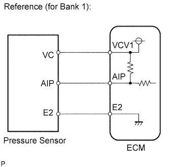
The ECM monitors the pressure in the secondary air passage using the pressure sensor located on the air switching valve in the secondary air injection system. Using this pressure value, the ECM determines whether the secondary air injection system is malfunctioning or not.
If there is a defect in the sensor or the sensor circuit, the voltage level deviates from the normal operating range. The ECM interprets this deviation as a malfunction in the pressure sensor or circuit and stores a DTC.
CONFIRMATION DRIVING PATTERN
- NOTICE:
- OK:
- No pending DTC is output.
| GTS Display | Description |
| NORMAL | DTC judgment completed System normal |
| ABNORMAL | DTC judgment completed System abnormal |
| INCOMPLETE | DTC judgment not completed Perform driving pattern after confirming DTC enabling conditions |
| N/A | Unable to perform DTC judgment Number of DTCs which do not fulfill DTC preconditions has reached ECU memory limit |
- HINT:
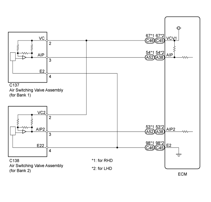
WIRING DIAGRAM
INSPECTION PROCEDURE
- HINT:
*: The No. 1 cylinder is the cylinder which is farthest from the transmission.
| 1.CHECK HARNESS AND CONNECTOR (PRESSURE SENSOR - ECM) |
Disconnect the air switching valve connector.
Disconnect the ECM connectors.
Measure the resistance according to the value(s) in the table below.
- Standard Resistance:
for RHD Tester Connection Condition Specified Condition C137-3 (AIP) - A52-54 (AIP) Always Below 1 Ω C137-2 (VC) - C46-67 (VCV1) Always Below 1 Ω C137-4 (E2) - C46-98 (E2) Always Below 1 Ω C138-3 (AIP2) - A52-53 (AIP2) Always Below 1 Ω C138-2 (VC2) - C46-67 (VCV1) Always Below 1 Ω C138-4 (E22) - C46-98 (E2) Always Below 1 Ω C137-3 (AIP) or A52-54 (AIP) - Body ground Always 10 kΩ or higher C137-2 (VC) or C46-67 (VCV1) - Body ground Always 10 kΩ or higher C138-3 (AIP2) or A52-53 (AIP2) - Body ground Always 10 kΩ or higher C138-2 (VC2) or C46-67 (VCV1) - Body ground Always 10 kΩ or higher
- Standard Resistance:
for LHD Tester Connection Condition Specified Condition C137-3 (AIP) - A38-54 (AIP) Always Below 1 Ω C137-2 (VC) - C45-67 (VCV1) Always Below 1 Ω C137-4 (E2) - C45-98 (E2) Always Below 1 Ω C138-3 (AIP2) - A38-53 (AIP2) Always Below 1 Ω C138-2 (VC2) - C45-67 (VCV1) Always Below 1 Ω C138-4 (E22) - C45-98 (E2) Always Below 1 Ω C137-3 (AIP) or A38-54 (AIP) - Body ground Always 10 kΩ or higher C137-2 (VC) or C45-67 (VCV1) - Body ground Always 10 kΩ or higher C138-3 (AIP2) or A38-53 (AIP2) - Body ground Always 10 kΩ or higher C138-2 (VC2) or C45-67 (VCV1) - Body ground Always 10 kΩ or higher
|
| ||||
| OK | |
| 2.CHECK TERMINAL VOLTAGE (VC OF AIR SWITCHING VALVE) |
Disconnect the air switching valve connector.
Turn the engine switch on (IG).
Measure the voltage according to the value(s) in the table below.
- Standard Resistance:
Tester Connection Condition Specified Condition C137-2 (VC) - C137-4 (E2) Engine switch on (IG) 4.5 to 5.5 V C138-2 (VC2) - C138-4 (E22) Engine switch on (IG) 4.5 to 5.5 V
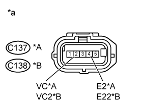
| *A | Bank 1 |
| *B | Bank 2 |
| *a | Front view of wire harness connector (to Air Switching Valve Assembly) |
|
| ||||
| OK | |
| 3.REPLACE AIR SWITCHING VALVE ASSEMBLY |
Replace the air switching valve assembly.
- HINT:
| NEXT | |
| 4.CHECK WHETHER DTC OUTPUT RECURS |
Perform the Confirmation Driving Pattern.
| Display (DTC Output) | Proceed to |
| NORMAL (No DTC output) | A |
| ABNORMAL (P2431, P2432, P2433, P2436, P2437 or P2438 output) | B |
|
| ||||
| A | ||
| ||