Land Cruiser URJ200 URJ202 GRJ200 VDJ200 - 3UR-FE ENGINE CONTROL
CHECK HARNESS AND CONNECTOR (A/F SENSOR - ECM)
CHECK WHETHER DTC OUTPUT RECURS
DTC P2237 Oxygen (A/F) Sensor Pumping Current Circuit / Open (Bank 1 Sensor 1)
DTC P2238 Oxygen (A/F) Sensor Pumping Current Circuit Low (Bank 1 Sensor 1)
DTC P2239 Oxygen (A/F) Sensor Pumping Current Circuit High (Bank 1 Sensor 1)
DTC P2240 Oxygen (A/F) Sensor Pumping Current Circuit / Open (Bank 2 Sensor 1)
DTC P2241 Oxygen (A/F) Sensor Pumping Current Circuit Low (Bank 2 Sensor 1)
DTC P2242 Oxygen (A/F) Sensor Pumping Current Circuit High (Bank 2 Sensor 1)
DTC P2252 Oxygen (A/F) Sensor Reference Ground Circuit Low (Bank 1 Sensor 1)
DTC P2253 Oxygen (A/F) Sensor Reference Ground Circuit High (Bank 1 Sensor 1)
DTC P2255 Oxygen (A/F) Sensor Reference Ground Circuit Low (Bank 2 Sensor 1)
DTC P2256 Oxygen (A/F) Sensor Reference Ground Circuit High (Bank 2 Sensor 1)
DESCRIPTION
Refer to DTC P0031 ().
| DTC Code | DTC Detection Condition | Trouble Area |
| P2237 P2240 | An open in the circuit between terminals A1A+ and A1A-/A2A+ and A2A- of the A/F sensor while the engine is running (2 trip detection logic). | Open in Air Fuel ratio (A/F) sensor (for Bank 1, 2 Sensor 1) circuit Air Fuel ratio (A/F) sensor (for Bank 1, 2 Sensor 1) ECM |
| P2238 P2241 | Case 1: (a) The A1A+/A2A+ voltage is 0.5 V or less. (b) (A1A+/A2A+) - (A1A-/A2A-) = 0.1 V or less. Case 2: | Open or short in A/F sensor (for Bank 1, 2 Sensor 1) circuit A/F sensor (for Bank 1, 2 Sensor 1) ECM |
| P2239 P2242 | The A1A+/A2A+ voltage is higher than 4.5 V for 5.0 seconds or more (2 trip detection logic). | Open or short in A/F sensor (for Bank 1, 2 Sensor 1) circuit A/F sensor (for Bank 1, 2 Sensor 1) ECM |
| P2252 P2255 | The A1A-/A2A- voltage is 0.5 V or less for 5.0 seconds or more (2 trip detection logic). | Open or short in A/F sensor (for Bank 1, 2 Sensor 1) circuit A/F sensor (for Bank 1, 2 Sensor 1) ECM |
| P2253 P2256 | The A1A-/A2A- voltage is higher than 4.5 V for 5.0 seconds or more (2 trip detection logic). | Open or short in A/F sensor (for Bank 1, 2 Sensor 1) circuit A/F sensor (for Bank 1, 2 Sensor 1) ECM |
- HINT:
MONITOR DESCRIPTION
These DTCs are stored when there is an open or short in the A/F sensor circuit, or if A/F sensor output drops.
To detect these problems, the voltage of the A/F sensor is monitored when turning the engine switch on (IG), and the admittance (admittance is an electrical term that indicates the ease of flow of current) is checked while driving. If the voltage of the A/F sensor is between 0.6 V and 4.5 V, it is considered normal. If the voltage is outside of the specified range, or the admittance is less than the standard value, the ECM will determine that there is a malfunction in the A/F sensor. If the same malfunction is detected in the next driving cycle, the MIL is illuminated and a DTC is stored.
The Air Fuel ratio (A/F) sensor varies its output voltage in proportion to the air-fuel ratio. If the A/F sensor impedance (alternating current resistance) or output voltage deviates greatly from the standard range, the ECM determines that there is an open or short in the A/F sensor circuit.
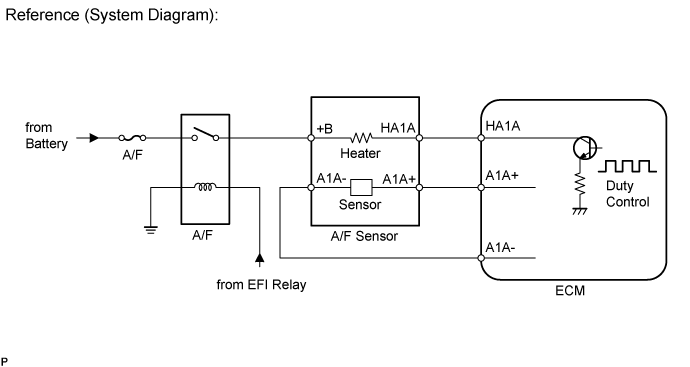
WIRING DIAGRAM
Refer to DTC P0031 ().
INSPECTION PROCEDURE
- HINT:
- Malfunctioning areas can be identified by performing the Control the Injection Volume for A/F sensor function provided in the Active Test. The Control the Injection Volume for A/F sensor function can help to determine whether the Air Fuel ratio (A/F) sensor, Heated Oxygen (HO2) sensor and other potential trouble areas are malfunctioning.
The following instructions describe how to conduct the Control the Injection Volume for A/F sensor operation using the intelligent tester.
- HINT:
- Standard:
Display Item
(Sensor)Injection Volume Status Voltage AFS B1 S1
(A/F)+25% Rich Below 3.0 -12.5% Lean Higher than 3.35 O2S B1 S2
(HO2)+25% Rich Higher than 0.55 -12.5% Lean Below 0.4 AFS B2 S1
(A/F)+25% Rich Below 3.0 -12.5% Lean Higher than 3.35 O2S B2 S2
(HO2)+25% Rich Higher than 0.55 -12.5% Lean Below 0.4
- NOTICE:
- The A/F sensor has an output delay of a few seconds and the HO2 sensor has a maximum output delay of approximately 20 seconds.
| Case | A/F Sensor (Sensor 1) Output Voltage | HO2 Sensor (Sensor 2) Output Voltage | Main Suspected Trouble Area |
| 1 | 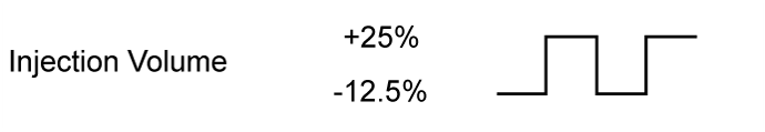 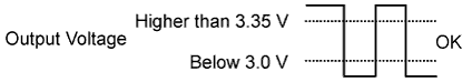 | 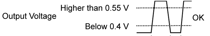 | - |
| 2 |  | | A/F sensor A/F sensor heater A/F sensor circuit |
| 3 | | | HO2 sensor HO2 sensor heater HO2 sensor circuit |
| 4 | | | Fuel injector Fuel pressure Gas leakage from exhaust system (Air-fuel ratio extremely rich or lean) |
- HINT:
*: The No. 1 cylinder is the cylinder which is farthest from the transmission.
| 1.CHECK HARNESS AND CONNECTOR (A/F SENSOR - ECM) |

Disconnect the C22 or C23 Air Fuel ratio (A/F) sensor connector.
Measure the voltage according to the value(s) in the table below.
| Tester Connection | Switch Condition | Specified Condition |
| C22-2 (+B) - Body ground | Engine switch on (IG) | 11 to 14 V |
| C23-2 (+B) - Body ground | Engine switch on (IG) | 11 to 14 V |
Turn the engine switch off.
Disconnect the C45 ECM connector.
Measure the resistance according to the value(s) in the table below.
| Tester Connection | Condition | Specified Condition |
| C22-1 (HA1A) - C45-22 (HA1A) | Always | Below 1 Ω |
| C22-3 (A1A+) - C45-126 (A1A+) | Always | Below 1 Ω |
| C22-4 (A1A-) - C45-125 (A1A-) | Always | Below 1 Ω |
| C23-1 (HA2A) - C45-20 (HA2A) | Always | Below 1 Ω |
| C23-3 (A2A+) - C45-103 (A2A+) | Always | Below 1 Ω |
| C23-4 (A2A-) - C45-102 (A2A-) | Always | Below 1 Ω |
| C22-1 (HA1A) or C45-22 (HA1A) - Body ground | Always | 10 kΩ or higher |
| C22-3 (A1A+) or C45- 126 (A1A+) - Body ground | Always | 10 kΩ or higher |
| C22-4 (A1A-) or C45-125 (A1A-) - Body ground | Always | 10 kΩ or higher |
| C23-1 (HA2A) or C45-20 (HA2A) - Body ground | Always | 10 kΩ or higher |
| C23-3 (A2A+) or C45- 103 (A2A+) - Body ground | Always | 10 kΩ or higher |
| C23-4 (A2A-) or C45-102 (A2A-) - Body ground | Always | 10 kΩ or higher |
|
| ||||
| OK | |
| 2.REPLACE AIR FUEL RATIO SENSOR |
Replace the air fuel ratio sensor ().
| NEXT | |
| 3.CHECK WHETHER DTC OUTPUT RECURS |
Connect the intelligent tester to the DLC3.
Turn the engine switch on (IG) and turn the tester on.
Clear DTCs ().
Start the engine.
Allow the engine to idle for 5 minutes or more.
Enter the following menus: Powertrain / Engine and ECT / DTC / Pending.
Read pending DTCs.
| Result | Proceed to |
| No DTC is output | A |
| P2237, P2238, P2239, P2240, P2241, P2242, P2252, P2253, P2255 or P2256 is output | B |
|
| ||||
| A | ||
| ||