Land Cruiser URJ200 URJ202 GRJ200 VDJ200 - 1UR-FE ENGINE CONTROL
CHECK AIR INJECTION CONTROL DRIVER (POWER SOURCE CIRCUIT)
CHECK HARNESS AND CONNECTOR (AIR INJECTION CONTROL DRIVER - ECM, BODY GROUND)
INSPECT AIR INJECTION CONTROL DRIVER (DI TERMINAL VOLTAGE)
REPLACE AIR INJECTION CONTROL DRIVER
CHECK WHETHER DTC OUTPUT RECURS
DTC P1613 Secondary Air Injection Driver Malfunction
DESCRIPTION
Refer to DTC P0412 ().
| DTC No. | DTC Detection Condition | Trouble Area |
| P1613 | Either condition (1) or (2) is met: (1) All conditions are met for 3 seconds or more (1 trip detection logic): Either the air pump or the air switching valve is not operating. Diagnostic signal from the air injection control driver is 80%. Battery voltage is 8 V or higher. Battery voltage is 8 V or higher. Diagnostic signal from the air injection control driver is abnormal (duty signal other than 0, 20, 40, 80 or 100%). | Air injection control driver Open in air injection control driver ground circuit |
All conditions met for 3 seconds or more (1 trip detection logic): Air injection system is operating (the air switching valve and air pump are on). Diagnostic signal from the air injection control driver is 0%. Battery voltage is 8 V or higher. | Short in diagnostic information signal circuit (Air injection control driver - ECM) Open or short in air pump and air switching valve command signal circuit (Air injection control driver - ECM) Open in air injection control driver ground circuit Air injection control driver ECM | |
Both conditions met for 3 seconds or more (1 trip detection logic): Battery voltage is 8 V or higher. Diagnostic signal from the air injection control driver is 100%. | Open or short in air injection control driver +B circuit Open in diagnostic information signal circuit (Air injection control driver - ECM) Air injection control driver ECM |
MONITOR DESCRIPTION
This DTC indicates an open or short circuit in the circuit containing the air pump of the secondary air injection system. The air injection control driver performs diagnosis of the air pump, air switching valve and itself, and sends the results of this diagnosis to the ECM as a duty signal. When the ECM receives a signal indicating a malfunction in the air pump, air switching valve or air injection control driver, it immediately illuminates the MIL and stores a DTC.
CONFIRMATION DRIVING PATTERN
- NOTICE:
- OK:
- No pending DTC is output.
| GTS Display | Description |
| NORMAL | DTC judgment completed System normal |
| ABNORMAL | DTC judgment completed System abnormal |
| INCOMPLETE | DTC judgment not completed Perform driving pattern after confirming DTC enabling conditions |
| N/A | Unable to perform DTC judgment Number of DTCs which do not fulfill DTC preconditions has reached ECU memory limit |
- HINT:
WIRING DIAGRAM
Refer to DTC P0412 ().
INSPECTION PROCEDURE
- HINT:
| 1.CHECK AIR INJECTION CONTROL DRIVER (POWER SOURCE CIRCUIT) |

Disconnect the air injection control driver connector.
Turn the engine switch on (IG).
Measure the voltage according to the value(s) in the table below.
- Standard Voltage:
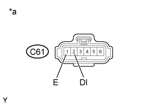
Tester Connection Switch Condition Specified Condition C61-5 (+B) - Body ground Engine switch on (IG) 11 to 14 V (near battery voltage)
| *a | Front view of wire harness connector (to Air Injection Control Driver) |
|
| ||||
| OK | |
| 2.CHECK HARNESS AND CONNECTOR (AIR INJECTION CONTROL DRIVER - ECM, BODY GROUND) |
Disconnect the ECM connector.
Disconnect the air injection control driver connector.
Measure the resistance according to the value(s) in the table below.
- Standard Resistance:
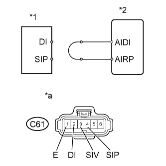
for RHD Tester Connection Condition Specified Condition C61-4 (SIP) - C46-54 (AIRP) Always Below 1 Ω C61-3 (SIV) - C46-28 (AIRV) Always Below 1 Ω C61-2 (DI) - C46-30 (AIDI) Always Below 1 Ω C61-1 (E) - Body ground Always Below 1 Ω C61-4 (SIP) or C46-54 (AIRP) - Body ground Always 10 kΩ or higher C61-3 (SIV) or C46-28 (AIRV) - Body ground Always 10 kΩ or higher C61-2 (DI) or C46-30 (AIDI) - Body ground Always 10 kΩ or higher for LHD Tester Connection Condition Specified Condition C61-4 (SIP) - C45-54 (AIRP) Always Below 1 Ω C61-3 (SIV) - C45-28 (AIRV) Always Below 1 Ω C61-2 (DI) - C45-30 (AIDI) Always Below 1 Ω C61-1 (E) - Body ground Always Below 1 Ω C61-4 (SIP) or C45-54 (AIRP) - Body ground Always 10 kΩ or higher C61-3 (SIV) or C45-28 (AIRV) - Body ground Always 10 kΩ or higher C61-2 (DI) or C45-30 (AIDI) - Body ground Always 10 kΩ or higher
|
| ||||
| OK | |
| 3.INSPECT AIR INJECTION CONTROL DRIVER (DI TERMINAL VOLTAGE) |
Disconnect the air injection control driver connector.
Turn the engine switch on (IG).
Measure the voltage according to the value(s) in the table below.
- Standard Voltage:
Tester Connection Switch Condition Specified Condition C61-2 (DI) - C61-1 (E) Engine switch on (IG) 11 to 14 V (near battery voltage)
| *a | Front view of wire harness connector (to Air Injection Control Driver) |
|
| ||||
| OK | |
| 4.PERFORM ACTIVE TEST USING GTS |

Disconnect the air injection control driver connector.
Connect terminals DI and SIV of the wire harness connector for the air injection control driver.
| *1 | Air Injection Control Driver |
| *2 | ECM |
| *a | Front view of wire harness connector (to Air Injection Control Driver) |
Connect the GTS to the DLC3.
Turn the engine switch on (IG) and turn the GTS on.
Enter the following menus: Powertrain / Engine and ECT / Utility / Secondary Air Injection Check / Manual Mode / AIR PUMP: ON, ASV 1: OPEN, ASV 2: OPEN.
- HINT:
- When Manual Mode is selected, the GTS initialization (atmospheric pressure measurement) is performed automatically. The initialization takes 10 seconds. After the initialization, AIR PUMP and ASV operation can be selected.
Start the engine.
Perform the secondary air injection system forced operation while the engine is idling.
Measure the voltage between the SIV and E terminals of the ECM connector when the secondary air injection system is ON and OFF.
Turn the engine switch off.
- NOTICE:
- Standard Voltage:
Tester Connection Condition Specified Condition C61-3 (SIV) - C61-1 (E) AIR PUMP: ON, ASV: OPEN 0.5 to 2 V C61-3 (SIV) - C61-1 (E) AIR PUMP: OFF, ASV: CLOSE 11 to 14 V
Connect terminals DI and SIP of the wire harness connector for the air injection control driver.
| *1 | Air Injection Control Driver |
| *2 | ECM |
| *a | Front view of wire harness connector (to Air Injection Control Driver) |
Connect the GTS to the DLC3.
Turn the engine switch on (IG) and turn the GTS on.
Enter the following menus: Powertrain / Engine and ECT / Utility / Secondary Air Injection Check / Manual Mode / AIR PUMP: ON, ASV 1: OPEN, ASV 2: OPEN.
- HINT:
- When Manual Mode is selected, the GTS initialization (atmospheric pressure measurement) is performed automatically. The initialization takes 10 seconds. After the initialization, AIR PUMP and ASV operation can be selected.
Start the engine.
Perform the secondary air injection system forced operation while the engine is idling.
Measure the voltage between the SIP and E terminals of the ECM connector when the secondary air injection system is ON and OFF.
Turn the engine switch off.
- NOTICE:
- Standard Voltage:
Tester Connection Condition Specified Condition C61-4 (SIP) - C61-1 (E) AIR PUMP: ON, ASV: OPEN 0.5 to 2 V C61-4 (SIP) - C61-1 (E) AIR PUMP: OFF, ASV: CLOSE 11 to 14 V
Reconnect the air injection control driver connector.
|
| ||||
| OK | |
| 5.REPLACE AIR INJECTION CONTROL DRIVER |
Replace the air injection control driver ().
| NEXT | |
| 6.CHECK WHETHER DTC OUTPUT RECURS |
Start the engine and warm it up.
Turn the engine switch off.
Connect the GTS to the DLC3.
Turn the engine switch on (IG).
Turn the GTS on.
Clear DTCs ().
Enter the following menus: Powertrain / Engine and ECT / Utility / Secondary air injection check / Automatic Mode.
Start the engine after the GTS initialization is finished.
Perform the System Check operation by pressing ENTER (Next).
After operating the secondary air injection system, perform the following to confirm the secondary air injection system pending codes: Press the Exit button.
Enter the following menus: Powertrain / Engine and ECT / DTC / Pending.
Read DTCs.
| Result | Proceed to |
| No output | A |
| Other DTCs are output | B |
Turn the engine switch off.
- NOTICE:
|
| ||||
| A | ||
| ||