Land Cruiser URJ200 URJ202 GRJ200 VDJ200 - 1VD-FTV ENGINE CONTROL
READ OUTPUT DTC (RECORD STORED DTC AND FREEZE FRAME DATA) (PROCEDURE 1)
CHECK FOR ANY OTHER DTCS OUTPUT (IN ADDITION TO DTC P1604)
TAKE SNAPSHOT DURING STARTING AND IDLING (PROCEDURE 3)
DETERMINE CAUSE OF PROBLEM (CHECK FREEZE FRAME DATA AND SNAPSHOT)
DTC P1604 Startability Malfunction
DESCRIPTION
This DTC is stored if the engine does not start or continues to crank without starting for a certain period of time. This DTC is also stored if the vehicle has run out of fuel. It is necessary to check whether there was enough fuel in the fuel tank before inspection.
| DTC Detection Drive Pattern | DTC Detection Condition | Trouble Area |
| After engine is started | Both conditions are met for 2 seconds or more*1: (1 trip detection logic) STA signal is input to the ECM. Engine speed is 500 rpm or less. | Battery Entry and start system Engine immobiliser system Irregular fuel Lack of fuel Suction control valve (fuel supply pump assembly) Injector assembly Fuel filter element sub-assembly Glow system No.1 or No. 2 injector driver Engine coolant temperature sensor Intake system Exhaust system Engine damaged, seized up Loss of compression Pressure discharge valve (common rail assembly (for bank 2)) Fuel pressure sensor (common rail assembly (for bank 1)) EGR system Diesel throttle system |
| After starting the engine (engine speed is 500 rpm or more), the engine speed drops to 200 rpm or less within 2 seconds. (1 trip detection logic) |
| DTC No. | Data List |
| P1604 | MAP MAF Intake Air Coolant Temp Battery Voltage Starter Signal Engine Speed of Cyl #1 (to #8) Immobiliser Communication Target Common Rail Pressure Common Rail Pressure Target Pump SCV Current Injection Feedback Val #1 (to #8) Injection Volume Actual Throttle Position Actual Throttle Position #2 Throttle Motor Duty Throttle Motor Duty #2 Target EGR Valve Pos Target EGR Valve Pos #2 Actual EGR Valve Pos Actual EGR Valve Pos #2 EGR Close Lrn. Val. EGR Close Lrn. Val #2 Glow Relay Request Glow Relay Request #2 |
INSPECTION PROCEDURE
- HINT:
As these DTCs can be stored as a result of certain user actions, even if these DTCs are output, if the customer makes no mention of problems, clear these DTCs without performing any troubleshooting and return the vehicle to the customer.
| In order to start the engine, the starting system, glow system, fuel system and the components related to compression must be functioning properly. |
| The cause of the problem can be narrowed down by checking if the engine cranks normally. |
| Starting system (when cranking is abnormal) |
The engine cannot be started if a sufficient cranking speed cannot be obtained. The following are possible causes of an insufficient cranking speed.
Problem with the entry and start system (Engine does not crank).
Problem with the immobiliser system (Engine does not crank).
Problem with the battery (Cranking speed is low).
Problem with the starter (Cranking speed is low).
| Glow system (when cranking is normal) |
When there is a problem with the glow system, the intake air temperature does not rise adequately and the fuel combustion temperature is not reached. Therefore, there is no initial combustion or it takes time for the engine to start. The following are possible causes.
Engine coolant temperature sensor malfunction.
Glow plug malfunction.
- HINT:
- If the glow plug has deteriorated, the engine may be less likely to start when the outside temperature is lower than 0°C (32°F).
Glow relay malfunction.
| Fuel system (when cranking is normal) |
The engine cannot be started if fuel is not supplied. A minimum fuel pressure of 25000 kPa or higher must be supplied to start the engine. The following are possible causes of insufficient fuel pressure.
Fuel line clog.
Lack of fuel.
Fuel frozen.
Low quality fuel.
Air in fuel pipe.
Fuel filter element sub-assembly clog.
Problem with fuel supply pump assembly.
Problem with common rail assemblies.
Problem with injector assemblies.
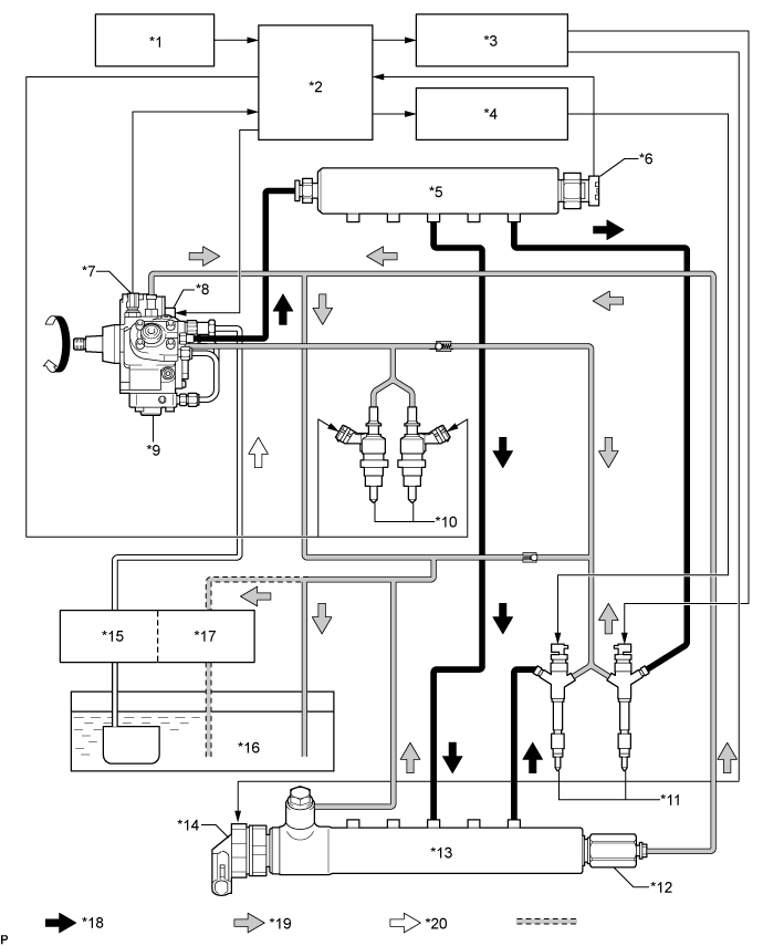
| *1 | Sensors | *2 | ECM |
| *3 | No. 1 Injector Driver | *4 | No. 2 Injector Driver |
| *5 | Common Rail Assembly (for Bank 1) | *6 | Fuel Pressure Sensor |
| *7 | Fuel Temperature Sensor | *8 | Suction Control Valve |
| *9 | Fuel Supply Pump Assembly | *10 | Exhaust Fuel Addition Injector Assembly |
| *11 | Injector Assembly | *12 | Pressure Limiter |
| *13 | Common Rail Assembly (for Bank 2) | *14 | Pressure Discharge Valve |
| *15 | Fuel Filter | *16 | Fuel Tank |
| *17 | Fuel Heater | *18 | High Pressure Fuel |
| *19 | Return Fuel | *20 | Suction Fuel |
| Engine assembly |
There may be a problem with the engine unit itself if there is no problem with cranking, the glow system or fuel system.
Engine friction too high.
Insufficient compression.
| 1.READ OUTPUT DTC (RECORD STORED DTC AND FREEZE FRAME DATA) (PROCEDURE 1) |
Connect the GTS to the DLC3.
Turn the engine switch on (IG) and turn the GTS on.
Enter the following menus: Engine and ECT / Trouble Codes.
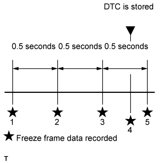
Record the stored DTCs and freeze frame data.
- HINT:
- Freeze frame data shows the actual engine conditions when engine starting trouble occurred.
| NEXT | |
| 2.CHECK FOR ANY OTHER DTCS OUTPUT (IN ADDITION TO DTC P1604) |
Connect the GTS to the DLC3.
Turn the engine switch on (IG) and turn the GTS on.
Enter the following menus: Engine and ECT / Trouble Codes.
Read the DTCs.
| Result | Proceed to |
| P1604 is output | A |
| P1604 and other DTCs are output | B |
- HINT:
- If any DTCs other than DTC P1604 are output, troubleshoot those DTCs first.
|
| ||||
| A | |
| 3.TAKE SNAPSHOT DURING STARTING AND IDLING (PROCEDURE 3) |
Connect the GTS to the DLC3.
Turn the engine switch on (IG) and turn the GTS on.
Enter the following menus: Engine and ECT / Data List / All Data.
Take a snapshot of the following Data List items with the GTS during "engine switch on (IG) (5 seconds) → Starting → Idling (10 seconds)".
| NEXT | |
| 4.DETERMINE CAUSE OF PROBLEM (CHECK FREEZE FRAME DATA AND SNAPSHOT) |
Determine the cause of the problem based on the freeze frame data recorded in procedure 1 and the Data List values recorded when starting the engine in procedure 3.
| Judgment of Data List Values | Problem Cause | Normal Condition | Diagnosis Note |
| "Coolant Temp" in freeze frame data is below 35°C (95°F) | Engine starting trouble which occurred with cold engine | - | The engine coolant temperature is 60 to 90°C (140 to 194°F) after warming up the engine. Normally, "Coolant Temp" is the same as the outside air temperature after an overnight engine soak. Engine starting trouble with a cold engine occurs when the engine coolant temperature sensor is malfunctioning. |
| "Coolant Temp" in freeze frame data is below 35°C (95°F). Currently, no engine starting trouble (cranking time less than 4 seconds) after warming up engine ("Coolant Temp" is 60°C (140°F) or higher). | Engine starting trouble which only occurs with cold engine |
| Judgment of Data List Values | Problem Cause | Normal Condition | Diagnosis Note |
| "Engine Speed" in freeze frame data is less than 120 rpm | Engine starting trouble may have occurred because engine speed was too low | During cranking: 120 to 400 rpm Idling with warm engine: 550 to 650 rpm | The battery may be fully depleted or the battery terminals may be loose. The viscosity of the engine oil may be inappropriate (low viscosity oil is not used). |
| "Engine Speed" in Data List is less than 120 rpm when cranking engine |
| Judgment of Data List Values | Problem Cause | Normal Condition | Diagnosis Note |
| "Battery Voltage" in freeze frame data is below 6 V | Engine starting trouble may have occurred because battery is fully depleted | During cranking: 6 V or higher | The battery may be fully depleted or the battery terminals may be loose. |
| "Battery Voltage" in Data List is below 6 V when cranking engine |
| Judgment of Data List Values | Problem Cause | Normal Condition | Diagnosis Note |
| "Common Rail Pressure" in freeze frame data is below 10000 kPa | Problem supplying fuel to fuel supply pump assembly (low pressure side) Ran out of fuel, air in fuel, fuel frozen (in this case, values of "Fuel Temperature" and "Coolant Temp" in freeze frame data are low) Fuel filter clog, fuel line clog (low pressure side) or fuel leak Feed pump (in fuel supply pump assembly) malfunctioning | When in a stable condition such as when the engine is idling after being warmed up, the fuel pressure is within +/-5000 kPa of the target fuel pressure | Disconnect the inlet hose from the fuel supply pump assembly (low pressure side), operate the hand pump and check that fuel is being supplied. |
| Common Rail Pressure is less than 10000 kPa from the value of Common Rail Pressure when cranking started | |||
| "Common Rail Pressure" in freeze frame data is below 25000 kPa | Problem supplying fuel to fuel supply pump assembly (low pressure side) or problem on high pressure side Fuel supply pump assembly (suction control valve operation malfunction) Common rail assembly Injector assembly (if glow plug is covered with fuel when removed, injector of corresponding cylinder may be stuck open) Fuel line clog (high pressure side), fuel leak | When in a stable condition such as when the engine is idling after being warmed up, the fuel pressure is within +/-5000 kPa of the target common rail pressure
| For startup at least 25000 kPa of fuel pressure is needed (there is a response lag when the pressure rises) If the fuel pressure is 10000 kPa or lower (when starting with an engine coolant temperature of 0°C (0°F) or lower, 15000 kPa or lower), fuel injection is stopped. |
| Common Rail Pressure is below Target Common Rail Pressure by 15000 kPa or more | |||
| Common Rail Pressure increases to a value that is higher than Target Common Rail Pressure immediately after cranking, and, remains higher than Target Common Rail Pressure | Injector assembly (fuel injection problem caused by air in injector) Problem with injection system | When in a stable condition such as when the engine is idling after being warmed up, the fuel pressure is within +/-5000 kPa of the target common rail pressure | If there is air in the injector assemblies for all cylinders, fuel cannot be injected. If there is an injection system problem related to 2 or more cylinders, fuel delivery and injection control are stopped. When the injector driver circuit has a malfunction (e.g. an EDU relay or fuse malfunction), the ECM cannot perform diagnosis of malfunctions and DTCs are not stored as voltage is unstable during cranking. Also, an excess amount of fuel is supplied by the fuel supply pump assembly and "Common Rail Pressure" becomes larger than "Target Common Rail Pressure" as fuel injection cannot be performed even though a fuel injection signal is output due to a failure to detect malfunctions at engine start. |
| Judgment of Data List Values | Problem Cause | Normal Condition | Diagnosis Note |
| "Injection Feedback Val #1 (to #8)" in freeze frame data is more than 3.0 mm3/st | Injector assembly malfunction or compression problem | -3.0 to 3.0 mm3/st | If an injector assembly is malfunctioning, even though the engine starts, idling is rough. |
| "Injection Feedback Val #1 (to #8)" in Data List is more than 3.0 mm3/st when idling |
| Judgment of Data List Values | Problem Cause | Normal Condition | Diagnosis Note |
| "Injection Volume" in Data List is more than 13 mm3/st and "Injection Feedback Val #1 (to #8)" is within range of +/-3.0 mm3/st when idling after warming up engine | Injector assemblies of all cylinders malfunctioning | - | - |
| Judgment of Data List Values | Problem Cause | Normal Condition | Diagnosis Note |
| "Main Injection Period" in freeze frame data or Data List is 0 μs | Fuel supply pump assembly (when SCV has open or short circuit, fuel supply from pump stops) Problem with engine immobiliser system Engine speed 60 rpm or less ECM malfunction | - | Indicates that fuel injection control has stopped. |
| Judgment of Data List Values | Problem Cause | Normal Condition | Diagnosis Note |
| "Immobiliser Communication" in freeze frame data or Data List is OFF | Engine immobiliser system | ON | Fuel injection has stopped due to engine immobiliser system. |
| Judgment of Data List Values | Problem Cause | Normal Condition | Diagnosis Note |
| "Immobiliser Fuel Cut History" in freeze frame data is OFF to ON | Fuel injection has stopped due to engine immobiliser system.
| OFF | Inspect engine immobiliser system. Inspection looseness in battery terminal. Inspect connection condition of ECM power supply system wiring. |
| Judgment of Data List Values | Problem Cause | Normal Condition | Diagnosis Note |
| "Stop Light Switch" in freeze frame data is OFF | Starting problems due to the brake pedal being released during cranking causing the power to the starter to be cut off and cranking to be insufficient. | ON | If there are no contact problems with the stop light switch signal circuit, the problem was probably due to operation by the user. |
| NEXT | ||
| ||