Land Cruiser URJ200 URJ202 GRJ200 VDJ200 - 1VD-FTV ENGINE CONTROL
READ VALUE USING GTS (EXHAUST TEMPERATURE)
READ VALUE USING GTS (CHECK FOR OPEN IN WIRE HARNESS)
REPLACE EXHAUST GAS TEMPERATURE SENSOR
CHECK HARNESS AND CONNECTOR (EXHAUST GAS TEMPERATURE SENSOR - ECM)
READ VALUE USING GTS (CHECK FOR SHORT IN WIRE HARNESS)
REPLACE EXHAUST GAS TEMPERATURE SENSOR
CHECK HARNESS AND CONNECTOR (EXHAUST GAS TEMPERATURE SENSOR - ECM)
REPAIR OR REPLACE HARNESS OR CONNECTOR
CONFIRM WHETHER MALFUNCTION HAS BEEN SUCCESSFULLY REPAIRED
DTC P0548 Exhaust Gas Temperature Sensor Circuit Low (Bank 2 Sensor 1)
DTC P0549 Exhaust Gas Temperature Sensor Circuit High (Bank 2 Sensor 1)
DTC P2035 Exhaust Gas Temperature Sensor Circuit Low (Bank 2 Sensor 2)
DTC P2036 Exhaust Gas Temperature Sensor Circuit High (Bank 2 Sensor 2)
DTC P2468 Exhaust Gas Temperature Sensor Circuit Low (Bank 2 Sensor 3)
DTC P2469 Exhaust Gas Temperature Sensor Circuit High (Bank 2 Sensor 3)
DESCRIPTION
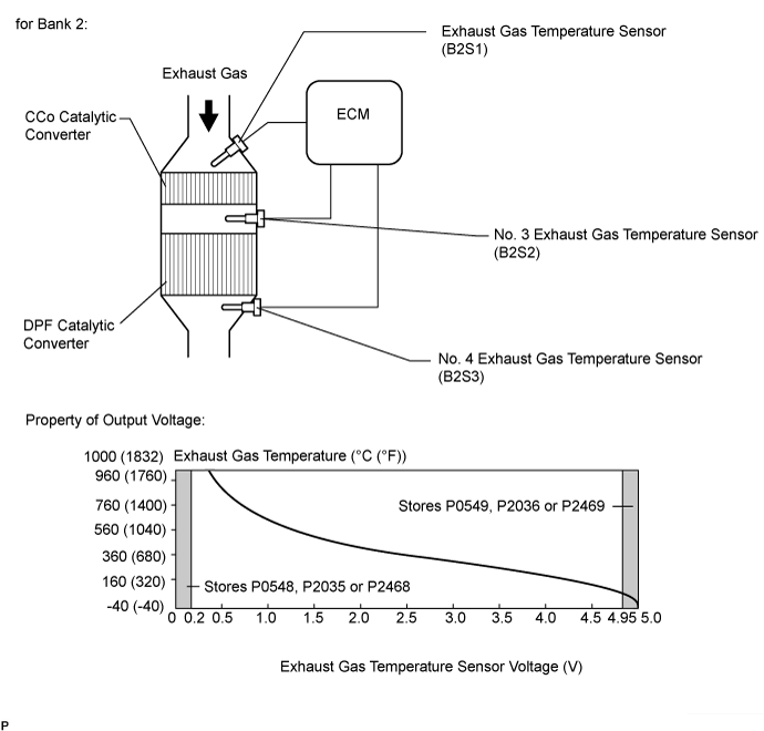
The exhaust gas temperature sensors are installed before and after the DPF catalytic converter and before the CCo catalytic converter to sense the exhaust gas temperature.
A thermistor built into the sensor changes its resistance value according to the exhaust gas temperature. The lower the exhaust gas temperature, the higher the thermistor resistance value. The higher the exhaust gas temperature, the lower the thermistor resistance value.
The exhaust gas temperature sensor is connected to the ECM. The 5 V power source voltage in the ECM is applied to the exhaust gas temperature sensor from terminal TCF2 (B2S1), TCI2 (B2S2) and TCO2 (B2S3) via resistor R.
Resistor R and the exhaust gas temperature sensor are connected in series. When the resistance value of the exhaust gas temperature sensor changes in accordance with the exhaust gas temperature, the voltage at terminals TCF2 (B2S1), TCI2 (B2S2) and TCO2 (B2S3) also changes. The exhaust gas temperature sensor monitors the temperature upstream of the CCo catalyst converter. The No. 3exhaust gas temperature sensor monitors the temperature upstream of the DPF catalyst converter. The No. 4 exhaust gas temperature sensor monitors the rise in temperature of the DPF catalyst converter. When PM forced regeneration is needed, the ECM operates the exhaust fuel addition injector assembly to obtain target upstream temperature of the DPF catalytic converter as monitored through sensor 2. In addition, the ECM monitors the temperature increase of the DPF catalytic converter using sensor 3.
| DTC Detection Drive Pattern | DTC Detection Condition | Trouble Area |
| Idle the engine for 3 seconds after warming up the engine (the engine coolant temperature is 60°C (140°F) or higher) and allowing 11 minutes to elapse after starting the engine. | Exhaust gas temperature sensor (B2S1) output voltage is below 0.2 V for 3 seconds or more when all conditions are met. (1 trip detection logic): After starting the engine, 11 minutes or more elapses Engine is running Coolant temperature is 60°C (140°F) or more | Open or short in exhaust gas temperature sensor (B2S1) circuit Exhaust gas temperature sensor (B2S1) ECM |
| DTC Detection Drive Pattern | DTC Detection Condition | Trouble Area |
| Idle the engine for 3 seconds after warming up the engine (the engine coolant temperature is 60°C (140°F) or higher) and allowing 11 minutes to elapse after starting the engine. | Exhaust gas temperature sensor (B2S1) output voltage is higher than 4.95 V for 3 seconds or more when all conditions are met. (1 trip detection logic): After starting the engine, 11 minutes or more elapses Engine is running Coolant temperature is 60°C (140°F) or more | Open or short in exhaust gas temperature sensor (B2S1) circuit Exhaust gas temperature sensor (B2S1) ECM |
| DTC Detection Drive Pattern | DTC Detection Condition | Trouble Area |
| Idle the engine for 3 seconds after warming up the engine (the engine coolant temperature is 60°C (140°F) or higher) and allowing 11 minutes to elapse after starting the engine. | No. 3 exhaust gas temperature sensor (B2S2) output voltage is below 0.2 V for 3 seconds or more when all conditions are met. (1 trip detection logic): After starting the engine, 11 minutes or more elapses Engine is running Coolant temperature is 60°C (140°F) or more | Open or short in No. 3 exhaust gas temperature sensor (B2S2) circuit No. 3 exhaust gas temperature sensor (B2S2) ECM |
| DTC Detection Drive Pattern | DTC Detection Condition | Trouble Area |
| Idle the engine for 3 seconds after warming up the engine (the engine coolant temperature is 60°C (140°F) or higher) and allowing 11 minutes to elapse after starting the engine. | No. 3 exhaust gas temperature sensor (B2S2) output voltage is higher than 4.95 V for 3 seconds or more when all conditions are met. (1 trip detection logic): After starting the engine, 11 minutes or more elapses Engine is running Coolant temperature is 60°C (140°F) or more | Open or short in No. 3 exhaust gas temperature sensor (B2S2) circuit No. 3 exhaust gas temperature sensor (B2S2) ECM |
| DTC Detection Drive Pattern | DTC Detection Condition | Trouble Area |
| Idle the engine for 3 seconds after warming up the engine (the engine coolant temperature is 60°C (140°F) or higher) and allowing 11 minutes to elapse after starting the engine. | No. 4 exhaust gas temperature sensor (B2S3) output voltage is below 0.2 V for 3 seconds or more when all conditions are met. (1 trip detection logic): After starting the engine, 11 minutes or more elapses Engine is running Coolant temperature is 60°C (140°F) or more | Open or short in No. 4 exhaust gas temperature sensor (B2S3) circuit No. 4 exhaust gas temperature sensor (B2S3) ECM |
| DTC Detection Drive Pattern | DTC Detection Condition | Trouble Area |
| Idle the engine for 3 seconds after warming up the engine (the engine coolant temperature is 60°C (140°F) or higher) and allowing 11 minutes to elapse after starting the engine. | No. 4 exhaust gas temperature sensor (B2S3) output voltage is higher than 4.95 V for 3 seconds or more when all conditions are met. (1 trip detection logic): After starting the engine, 11 minutes or more elapses Engine is running Coolant temperature is 60°C (140°F) or more | Open or short in No. 4 exhaust gas temperature sensor (B2S3) circuit No. 4 exhaust gas temperature sensor (B2S3) Abnormal rise in temperature due to melting of DPF catalytic converter ECM |
| DTC No. | Data List |
| P0548 P0549 | Exhaust Temperature B2S1 |
| P2035 P2036 | Exhaust Temperature B2S2 |
| P2468 P2469 | Exhaust Temperature B2S3 |
- HINT:
| Condition | Exhaust Gas Temperature | Exhaust Gas Temperature Sensor Condition |
| Idling after warm-up | Constant at between 50 and 700°C (122 and 1292°F) | Normal |
| -40°C (-40°F) | Open circuit | |
| 1000°C (1832°F) or higher | Short circuit |
MONITOR DESCRIPTION
The ECM constantly monitors the output voltages from the exhaust gas temperature sensors in order to detect problems with the sensors. When the sensor output voltage deviates from the normal operating range (between 0.2 V and 4.95 V) for more than 3 seconds after the engine is warmed up, the ECM interprets this as malfunction of the sensor circuit and illuminates the MIL.
WIRING DIAGRAM
Refer to DTC P0545 ().
INSPECTION PROCEDURE
- NOTICE:
- HINT:
| 1.READ VALUE USING GTS (EXHAUST TEMPERATURE) |
Connect the GTS to the DLC3.
Turn the engine switch on (IG) and turn the GTS on.
Enter the following menus: Engine and ECT / Data List / Exhaust Temperature B2S1, Exhaust Temperature B2S2 and Exhaust Temperature B2S3.
Read the value.
- Standard:
- Same as the actual exhaust gas temperature (50 to 700°C [122 to 1292°F] during idling after warm-up), and varies after an engine speed of 3000 rpm is maintained for 1 minute.
| Temperature Displayed | Proceed to |
| -40°C (-40°F) (After warming up the engine) | A |
| 1000°C (1832°F) or higher | B |
| OK: Same as the actual exhaust gas temperature (50 to 700°C [122 to 1292°F]) during idling after warm-up, and varies after maintaining an engine speed of 3000 rpm for 1 minute after accelerating the engine from idling to 3000 rpm | C |
- HINT:
|
| ||||
|
| ||||
| A | |
| 2.READ VALUE USING GTS (CHECK FOR OPEN IN WIRE HARNESS) |

Disconnect the C164, C165 or C167 exhaust gas temperature sensor connector.
Connect terminals 1 and 2 of the exhaust gas temperature sensor wire harness side connector.
Connect the GTS to the DLC3.
Turn the engine switch on (IG) and turn the GTS on.
Enter the following menus: Engine and ECT / Data List / Exhaust Temperature B2S1, Exhaust Temperature B2S2 and Exhaust Temperature B2S3.
Read the value.
- Standard:
- 1000°C (1832°F) or higher
| *1 | Exhaust Gas Temperature Sensor |
| *2 | ECM |
| *a | Front view of wire harness connector (to Exhaust Gas Temperature Sensor (B2S1)) |
| *b | Front view of wire harness connector (to No. 3 Exhaust Gas Temperature Sensor (B2S2)) |
| *c | Front view of wire harness connector (to No. 4 Exhaust Gas Temperature Sensor (B2S3)) |
Reconnect the exhaust gas temperature sensor connector.
|
| ||||
| OK | |
| 3.REPLACE EXHAUST GAS TEMPERATURE SENSOR |
Replace the exhaust gas temperature sensor (B2S1) ().
Replace the No. 3 exhaust gas temperature sensor (B2S2) ().
Replace the No. 4 exhaust gas temperature sensor (B2S3) ().
|
| ||||
| 4.CHECK HARNESS AND CONNECTOR (EXHAUST GAS TEMPERATURE SENSOR - ECM) |
Disconnect the exhaust gas temperature sensor connector.
Disconnect the ECM connector.
Measure the resistance according to the value(s) in the table below.
- Standard Resistance:
for LHD Tester Connection Condition Specified Condition C164-2 (TCF2) - C45-68 (TCF2) Always Below 1 Ω C164-1 (E2) - C45-99 (ETCF) Always Below 1 Ω C165-2 (TCI2) - C45-98 (TCI2) Always Below 1 Ω C165-1 (E2) - C45-99 (ETCF) Always Below 1 Ω C167-2 (TCO2) - C45-124 (TCO2) Always Below 1 Ω C167-1 (E2) - C45-99 (ETCF) Always Below 1 Ω for RHD Tester Connection Condition Specified Condition C164-2 (TCF2) - C46-68 (TCF2) Always Below 1 Ω C164-1 (E2) - C46-99 (ETCF) Always Below 1 Ω C165-2 (TCI2) - C46-98 (TCI2) Always Below 1 Ω C165-1 (E2) - C46-99 (ETCF) Always Below 1 Ω C167-2 (TCO2) - C46-124 (TCO2) Always Below 1 Ω C167-1 (E2) - C46-99 (ETCF) Always Below 1 Ω
Reconnect the exhaust gas temperature sensor connector.
Reconnect the ECM connector.
|
| ||||
| OK | |
| 5.REPLACE ECM |
Replace the ECM ().
|
| ||||
| 6.READ VALUE USING GTS (CHECK FOR SHORT IN WIRE HARNESS) |

Disconnect the C164, C165 or C167 exhaust gas temperature sensor connector.
Connect the GTS to the DLC3.
Turn the engine switch on (IG) and turn the GTS on.
Enter the following menus: Engine and ECT / Data List / Exhaust Temperature B2S1, Exhaust Temperature B2S2 and Exhaust Temperature B2S3.
Read the value.
- Standard:
- 0°C (32°F)
Reconnect the exhaust gas temperature sensor connector.
| *1 | Exhaust Gas Temperature Sensor |
| *2 | ECM |
Reconnect the exhaust gas temperature sensor connector.
|
| ||||
| OK | |
| 7.REPLACE EXHAUST GAS TEMPERATURE SENSOR |
Replace the exhaust gas temperature sensor (B2S1) ().
Replace the No. 3 exhaust gas temperature sensor (B2S2) ().
Replace the No. 4 exhaust gas temperature sensor (B2S3) ().
|
| ||||
| 8.CHECK HARNESS AND CONNECTOR (EXHAUST GAS TEMPERATURE SENSOR - ECM) |
Disconnect the exhaust gas temperature sensor connector.
Disconnect the ECM connector.
Measure the resistance according to the value(s) in the table below.
- Standard Resistance:
for LHD Tester Connection Condition Specified Condition C164-2 (TCF2) or C45-68 (TCF2) - Body ground Always 10 kΩ or higher C165-2 (TCI2) or C45-98 (TCI2) - Body ground Always 10 kΩ or higher C167-2 (TCO2) or C45-124 (TCO2) - Body ground Always 10 kΩ or higher for RHD Tester Connection Condition Specified Condition C164-2 (TCF2) or C46-68 (TCF2) - Body ground Always 10 kΩ or higher C165-2 (TCI2) or C46-98 (TCI2) - Body ground Always 10 kΩ or higher C167-2 (TCO2) or C46-124 (TCO2) - Body ground Always 10 kΩ or higher
Reconnect the exhaust gas temperature sensor connector.
Reconnect the ECM connector.
|
| ||||
| OK | |
| 9.REPLACE ECM |
Replace the ECM ().
|
| ||||
| 10.REPAIR OR REPLACE HARNESS OR CONNECTOR |
Repair or replace the harness or connector.
| NEXT | |
| 11.CONFIRM WHETHER MALFUNCTION HAS BEEN SUCCESSFULLY REPAIRED |
Connect the GTS to the DLC3.
Clear the DTCs ().
Start the engine.
Idle the engine for 3 seconds or more after warming up the engine (the engine coolant temperature is 60°C (140°F) or higher) and allowing 11 minutes to elapse after starting the engine.
Enter the following menus: Engine and ECT / Trouble Codes.
Confirm that the DTC is not output again.
| NEXT | ||
| ||