Land Cruiser URJ200 URJ202 GRJ200 VDJ200 - 1UR-FE ENGINE CONTROL
INSPECT AIR INJECTION VSV RELAY (AI-VSV)
CHECK AIR INJECTION VSV RELAY (AI-VSV) (POWER SOURCE)
CHECK HARNESS AND CONNECTOR (ECM - AIR INJECTION VSV RELAY (AI-VSV))
DTC P0416 Secondary Air Injection System Switching Valve "B" Circuit Open
DTC P0417 Secondary Air Injection System Switching Valve "B" Circuit Shorted
DESCRIPTION
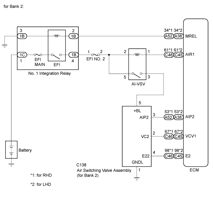
The ECM operates the air injection VSV relay (AI-VSV) which causes the air switching valve (for bank 2) to operate.
| DTC No. | DTC Detection Condition | Trouble Area |
| P0416 | Open or short in the air injection VSV relay (AI-VSV) circuit for 3 seconds (1 trip detection logic). | Open or short in air injection VSV relay (AI-VSV) circuit Air injection VSV relay (AI-VSV) ECM |
| P0417 | Open or short in the air injection VSV relay (AI-VSV) circuit for 3 seconds (1 trip detection logic). | Open or short in air injection VSV relay (AI-VSV) circuit Air injection VSV relay (AI-VSV) ECM |
MONITOR DESCRIPTION
These DTCs are designed to detect a malfunction in the air injection VSV (AI-VSV) relay circuit. When the system is normal, the battery voltage is applied to terminal AIR1 of the ECM while the air injection VSV (AI-VSV) relay is turned off, and the battery voltage is not applied to terminal AIR1 of the ECM while the air injection VSV (AI-VSV) relay is turned on. The ECM illuminates the MIL and stores a DTC when either one of the following conditions is detected.
CONFIRMATION DRIVING PATTERN
- NOTICE:
- OK:
- No pending DTC is output.
| GTS Display | Description |
| NORMAL | DTC judgment completed System normal |
| ABNORMAL | DTC judgment completed System abnormal |
| INCOMPLETE | DTC judgment not completed Perform driving pattern after confirming DTC enabling conditions |
| N/A | Unable to perform DTC judgment Number of DTCs which do not fulfill DTC preconditions has reached ECU memory limit |
- HINT:
WIRING DIAGRAM
INSPECTION PROCEDURE
- NOTICE:
- Inspect the fuses of circuits related to this system before performing the following inspection procedure.
- HINT:
- Read freeze frame data using the GTS. Freeze frame data records the engine condition when malfunctions are detected. When troubleshooting, freeze frame data can help determine if the vehicle was moving or stationary, if the engine was warmed up or not, if the air-fuel ratio was lean or rich, and other data from the time the malfunction occurred.
| 1.INSPECT AIR INJECTION VSV RELAY (AI-VSV) |
Inspect the air injection VSV relay (AI-VSV) ().
|
| ||||
| OK | |
| 2.CHECK AIR INJECTION VSV RELAY (AI-VSV) (POWER SOURCE) |
Remove the air injection VSV relay (AI-VSV).
Measure the voltage according to the value(s) in the table below.
- Standard Voltage:
Tester Connection Switch Condition Specified Condition Air injection VSV relay (AI-VSV) terminal 2 - Body ground Engine switch on (IG) 11 to 14 V Air injection VSV relay (AI-VSV) terminal 5 - Body ground Engine switch on (IG) 11 to 14 V
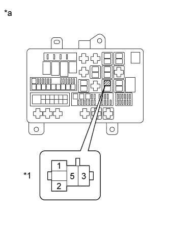
| *a | Engine Room Relay Block |
| *1 | Air Injection VSV Relay (AI-VSV) |
Reinstall the air injection VSV relay (AI-VSV).
|
| ||||
| OK | |
| 3.CHECK HARNESS AND CONNECTOR (ECM - AIR INJECTION VSV RELAY (AI-VSV)) |
Remove the air injection VSV relay (AI-VSV).
Disconnect the ECM connector.
Measure the resistance according to the value(s) in the table below.
- Standard Resistance:
for RHD Tester Connection Condition Specified Condition Air injection VSV relay (AI-VSV) terminal 1 - C46-61 (AIR1) Always Below 1 Ω Air injection VSV relay (AI-VSV) terminal 1 or C46-61 (AIR1) - Body ground Always 10 kΩ or higher for LHD Tester Connection Condition Specified Condition Air injection VSV relay (AI-VSV) terminal 1 - C45-61 (AIR1) Always Below 1 Ω Air injection VSV relay (AI-VSV) terminal 1 or C45-61 (AIR1) - Body ground Always 10 kΩ or higher
Reinstall the air injection VSV relay (AI-VSV).
Reconnect the ECM connector.
|
| ||||
| OK | ||
| ||