Land Cruiser URJ200 URJ202 GRJ200 VDJ200 - 1GR-FE ENGINE CONTROL
INSPECT NO. 1 EMISSION CONTROL VALVE SET
CHECK HARNESS AND CONNECTOR (NO. 1 EMISSION CONTROL VALVE SET - BODY GROUND)
DTC P0412 Secondary Air Injection System Switching Valve "A" Circuit
DESCRIPTION
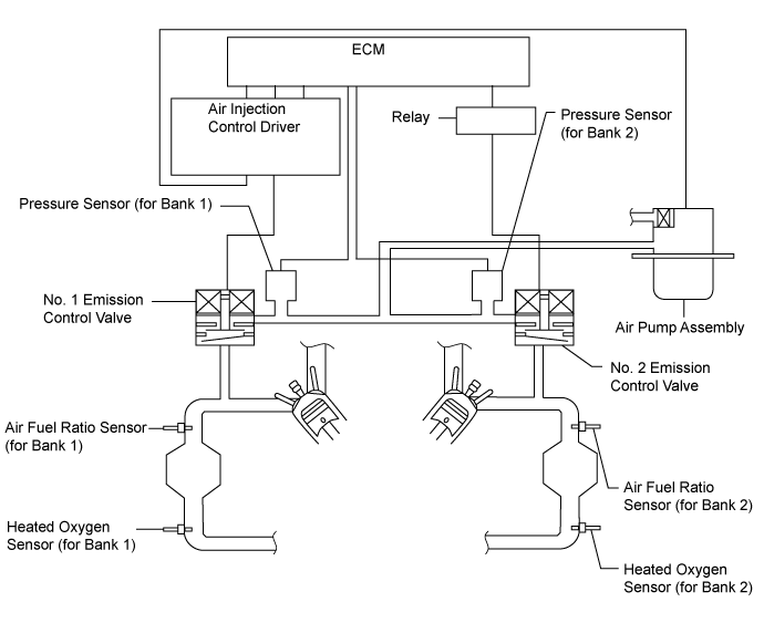
The secondary air injection system injects air into the exhaust port of the cylinder head using an electric air pump, starting when the engine is started cold and operating until the catalyst warms up, in order to promote combustion of unburned fuel and decrease the amount of hydrocarbons (HC) and carbon monoxide (CO) in the exhaust gas.
| DTC No. | DTC Detection Condition | Trouble Area |
| P0412 | All conditions are met for 3 seconds or more while idling immediately after the engine is started (1 trip detection logic): Secondary air injection system is not operating (the air pump and emission control valve are off). Diagnostic signal from the air injection control driver has a duty cycle of 40% (this indicates an open in the emission control valve circuit). Battery voltage is 8 V or higher. | Open in emission control valve drive circuit Air injection control driver assembly No. 1 emission control valve set ECM |
| P0412 | All conditions are met for 3 seconds or more while idling immediately after the engine is started (1 trip detection logic): Secondary air injection system is operating (the air pump and emission control valve are on). Diagnostic signal from the air injection control driver has a duty cycle of 40% (this indicates a short in the emission control valve circuit). Battery voltage is 8 V or higher. | Short between emission control valve drive circuit and body ground Air injection control driver assembly No. 1 emission control valve set ECM |
MONITOR DESCRIPTION
This DTC indicates an open or short circuit in the circuit containing the emission control valve of the secondary air injection system. The air injection control driver performs diagnosis of the air pump assembly, emission control valve set and itself, and sends the results of this diagnosis to the ECM as a duty signal. When the ECM receives a signal indicating a malfunction in the air pump, emission control valve set or air injection control driver, it illuminates the MIL and stores a DTC.
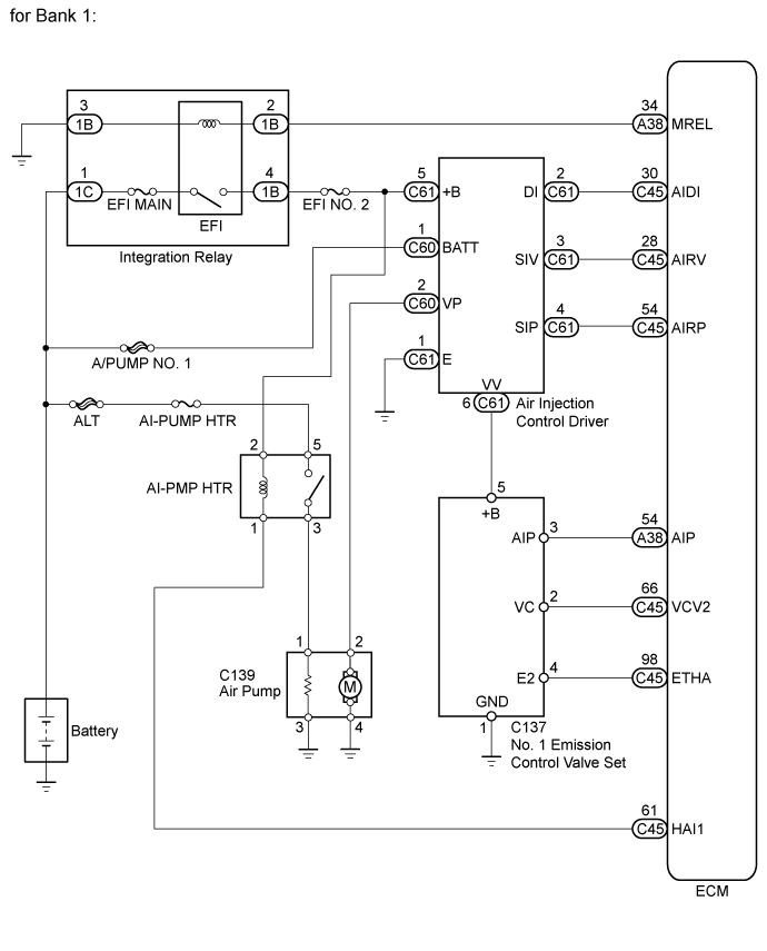
WIRING DIAGRAM
INSPECTION PROCEDURE
- HINT:
| 1.INSPECT NO. 1 EMISSION CONTROL VALVE SET |
Inspect the No. 1 emission control valve set ().
|
| ||||
| OK | |
| 2.CHECK HARNESS AND CONNECTOR (NO. 1 EMISSION CONTROL VALVE SET - BODY GROUND) |
Disconnect the No. 1 emission control valve set connector.
Measure the resistance according to the value(s) in the table below.
- Standard Resistance:
Tester Connection Condition Specified Condition C137-1 (GND) - Body ground Always Below 1 Ω
|
| ||||
| OK | |
| 3.CHECK HARNESS AND CONNECTOR (NO. 1 EMISSION CONTROL VALVE SET - AIR INJECTION CONTROL DRIVER ASSEMBLY) |
Disconnect the No. 1 emission control valve set connector.
Disconnect the air injection control driver assembly connector.
Measure the resistance according to the value(s) in the table below.
- Standard Resistance:
Tester Connection Condition Specified Condition C137-5 (+B) - C61-6 (VV) Always Below 1 Ω C137-5 (+B) or C61-6 (VV) - Body ground Always 10 kΩ or higher
|
| ||||
| OK | ||
| ||