Land Cruiser URJ200 URJ202 GRJ200 VDJ200 - 1VD-FTV ENGINE CONTROL
CHECK HARNESS AND CONNECTOR (FUEL PRESSURE SENSOR - ECM)
CHECK ECM (FUEL PRESSURE SENSOR VOLTAGE)
REPLACE COMMON RAIL ASSEMBLY (FOR BANK 1) (FUEL PRESSURE SENSOR)
CHECK WHETHER DTC OUTPUT RECURS (DTC P0087, P0190, P0192, P0193)
REPAIR OR REPLACE HARNESS OR CONNECTOR
CONFIRM WHETHER MALFUNCTION HAS BEEN SUCCESSFULLY REPAIRED
DTC P0087 Fuel Rail / System Pressure - Too Low
DTC P0190 Fuel Rail Pressure Sensor Circuit
DTC P0192 Fuel Rail Pressure Sensor Circuit Low Input
DTC P0193 Fuel Rail Pressure Sensor Circuit High Input
DESCRIPTION
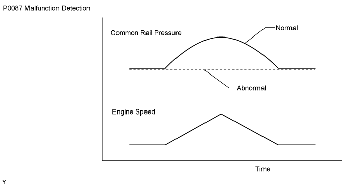
The ECM monitors the internal fuel pressure of the common rail assembly (for bank 1) using the fuel pressure sensor, and controls the suction control valve to regulate the internal pressure so that it reaches the target pressure. The pressure sensor is a semiconductor that varies electrical resistance when pressure is applied to its silicon chip. This sensor outputs a voltage in proportion to the internal fuel pressure.

| DTC Detection Drive Pattern | DTC Detection Condition | Trouble Area |
| After idling for 60 seconds, quickly increase engine speed to 2500 rpm repeatedly for 30 seconds | Fuel pressure sensor output voltage stays at a fixed value a certain number of times (0.1 seconds or more). (1 trip detection logic) | Open or short in fuel pressure sensor circuit Fuel pressure sensor (common rail assembly (for bank 1)) Ran out of fuel Fuel frozen ECM |
| DTC Detection Drive Pattern | DTC Detection Condition | Trouble Area |
| Engine switch on (IG) for 1 second | Fuel pressure sensor output voltage is 0.55 V or less, or 4.9 V or higher for 0.5 seconds. (1 trip detection logic) | Open or short in fuel pressure sensor circuit Fuel pressure sensor (common rail assembly (for bank 1)) ECM
|
| DTC Detection Drive Pattern | DTC Detection Condition | Trouble Area |
| Engine switch on (IG) for 1 second | Fuel pressure sensor output voltage is 0.55 V or less for 0.5 seconds. (1 trip detection logic) | Open or short in fuel pressure sensor circuit Fuel pressure sensor (common rail assembly (for bank 1)) ECM
|
| DTC Detection Drive Pattern | DTC Detection Condition | Trouble Area |
| Engine switch on (IG) for 1 second | Fuel pressure sensor output voltage is 4.9 V or higher for 0.5 seconds. (1 trip detection logic) | Open or short in fuel pressure sensor circuit Fuel pressure sensor (common rail assembly (for bank 1)) ECM
|
| DTC No. | Data List |
| P0087 P0190 P0192 P0193 | Common Rail Pressure Target Common Rail Pressure |
- HINT:
MONITOR DESCRIPTION
If this DTC is stored, the ECM enters fail-safe mode and limits engine power. The ECM continues operating in fail-safe mode until the engine switch is turned off.
These DTCs are stored if the fuel pressure sensor output voltage is out of the standard range due to an open or short malfunction of the sensor circuit.
If these DTCs are stored, the ECM enters fail-safe mode and limits the engine power. The ECM continues operating in fail-safe mode until the engine switch is turned off.
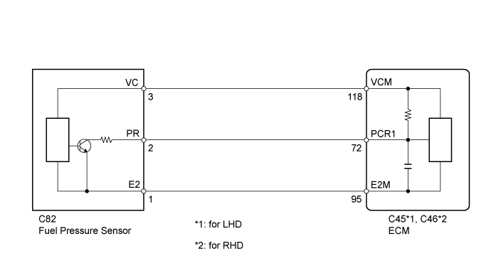
WIRING DIAGRAM
INSPECTION PROCEDURE
- NOTICE:
- HINT:
| 1.CHECK DTC OUTPUT |
Connect the GTS to the DLC3.
Turn the engine switch on (IG) and turn the GTS on.
Enter the following menus: Engine and ECT / Trouble Codes.
Read the DTCs.
| Result | Proceed to |
| P0190, P0192 or P0193 is output | A |
| P0087 is output | B |
|
| ||||
| A | |
| 2.CHECK HARNESS AND CONNECTOR (FUEL PRESSURE SENSOR - ECM) |
Disconnect the fuel pressure sensor connector.
Disconnect the ECM connector.
Measure the resistance according to the value(s) in the table below.
- Standard Resistance:
for LHD Tester Connection Condition Specified Condition C82-2 (PR) - C45-72 (PCR1) Always Below 1 Ω C82-3 (VC) - C45-118 (VCM) Always Below 1 Ω C82-1 (E2) - C45-95 (E2M) Always Below 1 Ω C82-2 (PR) or C45-72 (PCR1) - Body ground Always 10 kΩ or higher C82-3 (VC) or C45-118 (VCM) - Body ground Always 10 kΩ or higher for RHD Tester Connection Condition Specified Condition C82-2 (PR) - C46-72 (PCR1) Always Below 1 Ω C82-3 (VC) - C46-118 (VCM) Always Below 1 Ω C82-1 (E2) - C46-95 (E2M) Always Below 1 Ω C82-2 (PR) or C46-72 (PCR1) - Body ground Always 10 kΩ or higher C82-3 (VC) or C46-118 (VCM) - Body ground Always 10 kΩ or higher
|
| ||||
| OK | |
| 3.CHECK ECM (FUEL PRESSURE SENSOR VOLTAGE) |
Disconnect the fuel pressure sensor connector.
Measure the voltage according to the value(s) in the table below.
- Standard Voltage:
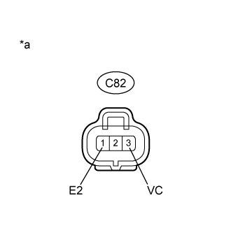
Tester Connection Switch Condition Specified Condition C82-3 (VC) - C82-1 (E2) Engine switch on (IG) 4.5 to 5.5 V
| *a | Front view of wire harness connector (to Fuel Pressure Sensor) |
|
| ||||
| OK | |
| 4.REPLACE COMMON RAIL ASSEMBLY (FOR BANK 1) (FUEL PRESSURE SENSOR) |
Replace the common rail assembly (for bank 1) ().
| NEXT | |
| 5.BLEED AIR FROM FUEL SYSTEM |
Bleed the air from the fuel system ().
Perform PM forced regeneration ().
- HINT:
- When fuel lines are disconnected, air may enter the fuel lines, leading to engine starting trouble. Therefore, perform forced regeneration and bleed the air from the fuel lines.
| NEXT | |
| 6.CHECK WHETHER DTC OUTPUT RECURS (DTC P0087, P0190, P0192, P0193) |
Connect the GTS to the DLC3.
Turn the engine switch on (IG) and turn the GTS on.
Clear the DTCs ().
Let the engine idle for 60 seconds, and then quickly increase the engine speed to 2500 rpm repeatedly for 30 seconds.
Enter the following menus: Engine and ECT / Trouble Codes.
Read the DTCs.
| Result | Proceed to |
| P0087, P0190, P0192 or P0193 is output | A |
| No DTC is output | B |
|
| ||||
| A | |
| 7.REPLACE ECM |
Replace the ECM ().
|
| ||||
| 8.REPAIR OR REPLACE HARNESS OR CONNECTOR |
Repair or replace the harness or connector.
| NEXT | |
| 9.CONFIRM WHETHER MALFUNCTION HAS BEEN SUCCESSFULLY REPAIRED |
Connect the GTS to the DLC3.
Clear the DTCs ().
Turn the engine switch off for 30 seconds or more.
Turn the engine switch on (IG).
Let the engine idle for 60 seconds, and then quickly increase the engine speed to 2500 rpm repeatedly for 30 seconds.
Confirm that the DTC is not output again.
- HINT:
- Perform the following procedure using the GTS to determine whether or not the DTC judgment has been carried out.
Enter the following menus: Engine and ECT / Utility / All Readiness.
Input DTC P0087, P0190, P0192 or P0193.
Check that STATUS is NORMAL. If STATUS is INCOMPLETE or N/A, increase the idling time.
| NEXT | ||
| ||