Land Cruiser URJ200 URJ202 GRJ200 VDJ200 - 1UR-FE ENGINE CONTROL
INSPECT HEATED OXYGEN SENSOR (HEATER RESISTANCE)
CHECK TERMINAL VOLTAGE (+B OF HEATED OXYGEN SENSOR)
CHECK HARNESS AND CONNECTOR (HEATED OXYGEN SENSOR - ECM)
CHECK WHETHER DTC OUTPUT RECURS
INSPECT NO. 1 INTEGRATION RELAY (EFI)
CHECK HARNESS AND CONNECTOR (HEATED OXYGEN SENSOR - NO. 1 INTEGRATION RELAY)
DTC P0037 Oxygen Sensor Heater Control Circuit Low (Bank 1 Sensor 2)
DTC P0038 Oxygen Sensor Heater Control Circuit High (Bank 1 Sensor 2)
DTC P0057 Oxygen Sensor Heater Control Circuit Low (Bank 2 Sensor 2)
DTC P0058 Oxygen Sensor Heater Control Circuit High (Bank 2 Sensor 2)
DTC P102D O2 Sensor Heater Circuit Performance Bank 1 Sensor 2 Stuck ON
DTC P105D O2 Sensor Heater Circuit Performance Bank 2 Sensor 2 Stuck ON
DESCRIPTION
- HINT:
| DTC No. | DTC Detection Condition | Trouble Area |
| P0037 P0057 | The heater current is below the specified value while the heater is operating (1 trip detection logic). | Open in heated oxygen sensor heater circuit Heated oxygen sensor heater (for Sensor 2) No. 1 integration relay ECM |
| P0038 P0058 | The heater current is higher than the specified value while the heater is operating (1 trip detection logic). | Short in heated oxygen sensor heater circuit Heated oxygen sensor heater (for Sensor 2) No. 1 integration relay ECM |
| P102D P105D | The heater current is higher than the specified value while the heater is not operating (1 trip detection logic). | ECM |
MONITOR DESCRIPTION
The sensing portion of the heated oxygen sensor has a zirconia element which is used to detect the oxygen concentration in the exhaust gas. If the zirconia element is at the appropriate temperature and the difference between the oxygen concentrations surrounding the inside and outside surfaces of the sensor is large, the zirconia element generates voltage signals. In order to increase the oxygen concentration detecting capacity of the zirconia element, the ECM supplements the heat from the exhaust with heat from a heating element inside the sensor.
The ECM monitors the current applied to the heated oxygen sensor heater to check the heater for malfunctions.
If the heater current is outside the normal range, the signal transmitted by the heated oxygen sensor becomes inaccurate. When the current in the heated oxygen sensor heater is outside the normal operating range, the ECM interprets this as a malfunction in the sensor heater and stores a DTC.
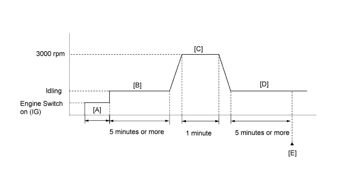
CONFIRMATION DRIVING PATTERN
- HINT:
| GTS Display | Description |
| NORMAL | DTC judgment completed System normal |
| ABNORMAL | DTC judgment completed System abnormal |
| INCOMPLETE | DTC judgment not completed Perform driving pattern after confirming DTC enabling conditions |
| N/A | Unable to perform DTC judgment Number of DTCs which do not fulfill DTC preconditions has reached ECU memory limit |
- HINT:
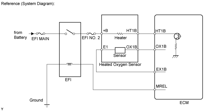
WIRING DIAGRAM
Refer to DTC P0136 ().
INSPECTION PROCEDURE
- NOTICE:
- Inspect the fuses of circuits related to this system before performing the following inspection procedure.
- HINT:
*: The No. 1 cylinder is the cylinder which is farthest from the transmission.
| 1.INSPECT HEATED OXYGEN SENSOR (HEATER RESISTANCE) |
Inspect the heated oxygen sensor ().
|
| ||||
| OK | |
| 2.CHECK TERMINAL VOLTAGE (+B OF HEATED OXYGEN SENSOR) |
Disconnect the heated oxygen sensor connector.
Turn the engine switch on (IG).
Measure the voltage according to the value(s) in the table below.
- Standard Voltage:
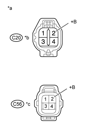
Tester Connection Switch Condition Specified Condition C20-2 (+B) - Body ground Engine switch on (IG) 11 to 14 V C56-2 (+B) - Body ground Engine switch on (IG) 11 to 14 V
| *a | Front view of wire harness connector (to Heated Oxygen Sensor) |
| *b | Bank 1 sensor 2 |
| *c | Bank 2 sensor 2 |
|
| ||||
| OK | |
| 3.CHECK HARNESS AND CONNECTOR (HEATED OXYGEN SENSOR - ECM) |
Disconnect the heated oxygen sensor connector.
Disconnect the ECM connector.
Measure the resistance according to the value(s) in the table below.
- Standard Resistance:
for RHD Tester Connection Condition Specified Condition C20-1 (HT1B) - C46-45 (HT1B) Always Below 1 Ω C56-1 (HT2B) - C46-44 (HT2B) Always Below 1 Ω C20-1 (HT1B) or C46-45 (HT1B) - Body ground Always 10 kΩ or higher C56-1 (HT2B) or C46-44 (HT2B) - Body ground Always 10 kΩ or higher for LHD Tester Connection Condition Specified Condition C20-1 (HT1B) - C45-45 (HT1B) Always Below 1 Ω C56-1 (HT2B) - C45-44 (HT2B) Always Below 1 Ω C20-1 (HT1B) or C45-45 (HT1B) - Body ground Always 10 kΩ or higher C56-1 (HT2B) or C45-44 (HT2B) - Body ground Always 10 kΩ or higher
|
| ||||
| OK | |
| 4.CHECK WHETHER DTC OUTPUT RECURS |
Connect the GTS to the DLC3.
Turn the engine switch on (IG).
Turn the GTS on.
Clear DTCs ().
Start the engine.
Drive the vehicle in accordance with the driving pattern described in Confirmation Driving Pattern.
Read the output pending DTCs using the GTS.
| Result | Proceed to |
| No pending DTC is output | A |
| Pending DTC P0037, P0038, P0057, P0058, P102D and/or P105D is output | B |
|
| ||||
| A | ||
| ||
| 5.INSPECT NO. 1 INTEGRATION RELAY (EFI) |
Inspect the No. 1 integration relay (EFI) ().
|
| ||||
| OK | |
| 6.CHECK HARNESS AND CONNECTOR (HEATED OXYGEN SENSOR - NO. 1 INTEGRATION RELAY) |
Disconnect the heated oxygen sensor connector.
Remove the No. 1 integration relay from the engine room relay block.
Measure the resistance according to the value(s) in the table below.
- Standard Resistance:
Tester Connection Condition Specified Condition C20-2 (+B) - 1B-4 Always Below 1 Ω C56-2 (+B) - 1B-4 Always Below 1 Ω C20-2 (+B) or 1B-4 - Body ground Always 10 kΩ or higher C56-2 (+B) or 1B-4 - Body ground Always 10 kΩ or higher
|
| ||||
| OK | ||
| ||