Land Cruiser URJ200 URJ202 GRJ200 VDJ200 - BRAKE CONTROL / DYNAMIC CONTROL SYSTEMS
VEHICLE STABILITY CONTROL SYSTEM - TEST MODE PROCEDURE
- NOTICE:
- HINT:
| TEST MODE (SIGNAL CHECK) PROCEDURE |
When using the GTS:
Place the vehicle on a level surface with an inclination of less than 1%.
Turn the ignition switch off.
Check that the shift lever is in P.
- CAUTION:
- Apply the parking brake for safety.
Connect the GTS to the DLC3.
Turn the ignition switch to ON.
Turn the GTS on.
Enter the following menus: Chassis / ABS/VSC/TRC / Utility / Signal Check.
Check that the ABS warning light and slip indicator light blink at 0.125 second intervals (0.125 seconds on and 0.125 seconds off).
Start the engine.
When using SST check wire:
Place the vehicle on a level surface with an inclination of less than 1%.
Turn the ignition switch off.
Check that the shift lever is in P.
- CAUTION:
- Apply the parking brake for safety.
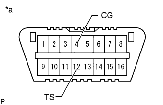
Using SST, connect terminals 12 (TS) and 4 (CG) of the DLC3.
- SST
- 09843-18040
| *a | Front view of DLC3 |
Turn the ignition switch to ON.
Check that the ABS warning light and slip indicator light blink at 0.125 second intervals (0.125 seconds on and 0.125 seconds off).
Start the engine.
ABS Signal Check
- HINT:
- Check that the ABS warning light is blinking in the test mode blinking pattern (0.125 seconds on and 0.125 seconds off) before performing the ABS signal check.
Master Cylinder Pressure Sensor and Acceleration Sensor Check
Keep the vehicle stationary on a level surface for 1 second or more.
With the vehicle stationary, release the brake pedal for 1 second or more, and then quickly depress the brake pedal with a force of 98 N (10 kgf, 22 lbf) or more for 1 second.
Check that the ABS warning light comes on for 3 seconds.
- HINT:
- During test mode, the ABS warning light turns on for 3 seconds every time the above operation is performed.
Center Differential Lock Detection Switch Check
Press the center differential lock switch to lock the center differential.
- HINT:
- Move the vehicle either forward or backward a little to engage the center differential lock.
Press the center differential lock switch to unlock the center differential.
Speed Sensor Check
- NOTICE:
Drive the vehicle straight forward at a speed of 45 km/h (28 mph) or more for several seconds (forward signal check).
Check that the ABS warning light goes off.
Drive the vehicle in reverse for more than 1 second at 3 km/h (2 mph) or more (reverse signal check).
Check that the ABS warning light goes off.
- HINT:
- Drive the vehicle in reverse and check the speed sensor signal. Note that the signal check cannot be completed if the vehicle speed is 45 km/h (28 mph) or more.
- NOTICE:
Stop the vehicle.
- NOTICE:
- HINT:
- When the signal check is completed, the ABS warning light goes off while driving and blinks in the test mode pattern while stationary.
VSC Signal Check
- HINT:
- Check that the slip indicator light is blinking in the test mode blinking pattern (0.125 seconds on and 0.125 seconds off) before performing the VSC signal check.
Stop light Switch Check (w/ Dynamic Radar Cruise Control System)
Check that the shift lever is in P.
Release the brake pedal for 1 second or more with the vehicle stopped, and then depress the brake pedal with a force of 50 N (5 kgf, 11 lbf) or more.
Check that a buzzer sounds for 3 seconds.
Turn Assist Function Switch Check

Push and hold the turn assist function switch.
| *1 | Suspension Control Switch |
| *2 | Turn Assist Function Switch |
Check that the turn assist indicator light comes on.
Release the turn assist function switch to turn the turn assist indicator light off.
CRAWL Switch Check
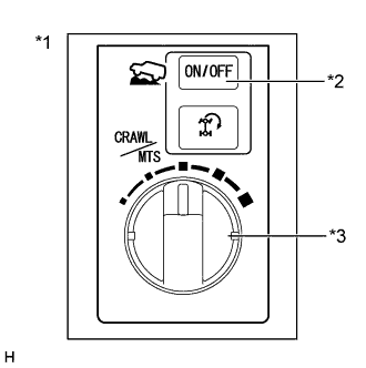
Push the CRAWL ON/OFF switch.
- HINT:
- The CRAWL indicator light illuminates while the CRAWL ON/OFF switch is pushed.
| *1 | Suspension Control Switch |
| *2 | CRAWL ON/OFF Switch |
| *3 | CRAWL Speed Selector Switch |

Turn the speed selector switch to low.
| *a | Low |
| *b | Medium-low |
| *c | Medium |
| *d | Medium-high |
| *e | High |
Turn the speed selector switch to medium-low.
Turn the speed selector switch to medium.
Turn the speed selector switch to medium-high.
Turn the speed selector switch to high.
Turn the speed selector switch to low.
VSC OFF Switch Check
Press the VSC OFF switch.
Check that the VSC OFF indicator light comes on.
Press the VSC OFF switch again to turn the VSC OFF indicator light off.
End of Signal Check
If the signal check is completed, the ABS warning light and slip indicator light blink (0.125 seconds on and 0.125 seconds off) when the vehicle is stopped and goes off while driving the vehicle.
- NOTICE:
- If the signal check is not completed, the ABS warning light blinks while driving and the ABS does not operate.
Read test mode (signal check) DTCs (when using the GTS).
Read the DTC(s) by following the GTS screen.
- NOTICE:
- HINT:
- Refer to Signal Check DTCs.
Turn the ignition switch off and disconnect the GTS.
Read test mode (signal check) DTCs (when using SST check wire).
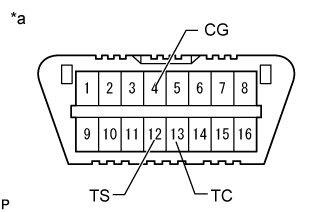
Using SST, connect terminals 13 (TC), 12 (TS) and 4 (CG) of the DLC3.
- SST
- 09843-18040
| *a | Front view of DLC3 |
Read the number of blinks of the ABS warning light and slip indicator light.
- HINT:
Disconnect SST from terminals 13 (TC), 12 (TS) and 4 (CG) of the DLC3.
| LIST OF TEST MODE (SIGNAL CHECK) DTC |
| DTC Code | Detection Item | Trouble Area | |
| GTS Display | ABS Warning Light Display | ||
| C1271 | 71 | Front Speed Sensor RH Output Voltage Malfunction | Front speed sensor RH Sensor installation Speed sensor rotor |
| C1272 | 72 | Front Speed Sensor LH Output Voltage Malfunction | Front speed sensor LH Sensor installation Speed sensor rotor |
| C1273 | 73 | Rear Speed Sensor RH Output Voltage Malfunction | Rear speed sensor RH Sensor installation Speed sensor rotor |
| C1274 | 74 | Rear Speed Sensor LH Output Voltage Malfunction | Rear speed sensor LH Sensor installation Speed sensor rotor |
| C1275 | 75 | Abnormal Change in Output Signal of Front Speed Sensor RH | Front speed sensor RH Speed sensor rotor |
| C1276 | 76 | Abnormal Change in Output Signal of Front Speed Sensor LH | Front speed sensor LH Speed sensor rotor |
| C1277 | 77 | Abnormal Change in Output Signal of Rear Speed Sensor RH | Rear speed sensor RH Speed sensor rotor |
| C1278 | 78 | Abnormal Change in Output Signal of Rear Speed Sensor LH | Rear speed sensor LH Speed sensor rotor |
| C1279 | 79 | G Sensor Output Voltage Malfunction | ECU-IG No. 2 fuse Sensor installation Harness or connector Acceleration sensor (Yaw rate sensor assembly) CAN communication system |
| C1281 | 81 | Master Cylinder Pressure Sensor Output Malfunction | Master cylinder solenoid (Master cylinder pressure sensor) |
| C1282 | 82 | Center Differential Lock Position Switch Malfunction | Harness or connector Transfer system |
| DTC Code | Detection Item | Trouble Area | |
| GTS Display | Slip Indicator Light Display | ||
| C1379 | 74 | Malfunction in CRAWL switch | CRAWL switch (Suspension control switch) Harness or connector Skid control ECU (Master cylinder solenoid) |