DESCRIPTION
WIRING DIAGRAM
INSPECTION PROCEDURE
CHECK DTC
CHECK CAN COMMUNICATION LINE
READ VALUE USING GTS (PARKING BRAKE SW)
PERFORM ACTIVE TEST USING GTS (BRAKE WARNING LIGHT)
INSPECT PARKING BRAKE SWITCH
CHECK HARNESS AND CONNECTOR (PARKING BRAKE SWITCH - MAIN BODY ECU)
ANTI-LOCK BRAKE SYSTEM - Brake Warning Light Remains ON
DESCRIPTION
The brake warning light comes on when brake fluid is insufficient, the parking brake is applied or the EBD is defective.
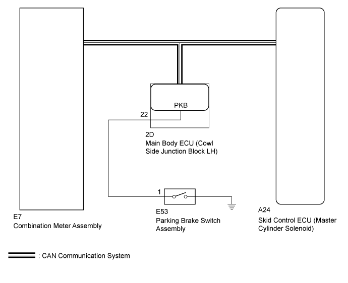
WIRING DIAGRAM
INSPECTION PROCEDURE
- After replacing the master cylinder solenoid, perform calibration ().
Check for DTCs ().
Result| Result | Proceed to |
| DTC is not output | A |
| DTC is output | B |
| | REPAIR CIRCUITS INDICATED BY OUTPUT DTCS ()
|
|
|
| 2.CHECK CAN COMMUNICATION LINE
|
Turn the ignition switch off.
Connect the GTS to the DLC3.
Turn the ignition switch to ON.
Select CAN Bus Check from the System Selection Menu screen and follow the prompts on the screen to inspect the CAN bus.
- OK:
- CAN Bus Check indicates no malfunctions in CAN communication.
Result| Result | Proceed to |
| OK | A |
| NG (for LHD) | B |
| NG (for RHD) | C |
| | GO TO CAN COMMUNICATION SYSTEM (HOW TO PROCEED WITH TROUBLESHOOTING) ()
|
|
|
| | GO TO CAN COMMUNICATION SYSTEM (HOW TO PROCEED WITH TROUBLESHOOTING) ()
|
|
|
| 3.READ VALUE USING GTS (PARKING BRAKE SW) |
Turn the ignition switch off.
Connect the GTS to the DLC3.
Turn the ignition switch to ON.
Enter the following menus: Chassis / ABS/VSC/TRC / Data List.
ABS/VSC/TRC| Tester Display | Measurement Item/Range | Normal Condition | Diagnostic Note |
| Parking Brake SW | Parking brake switch/ ON or OFF | ON: Parking brake applied
OFF: Parking brake released | - |
Using the GTS, check the input of the switch operation when the parking brake pedal is operated.
- OK:
- When the parking brake is operated, the display changes as shown above.
| 4.PERFORM ACTIVE TEST USING GTS (BRAKE WARNING LIGHT) |
Turn the ignition switch off.
Connect the GTS to the DLC3.
Turn the ignition switch to ON.
Enter the following menus: Chassis / ABS/VSC/TRC / Active Test.
ABS/VSC/TRC| Tester Display | Test Part | Control Range | Diagnostic Note |
| Brake Warning Light | Brake warning light | Warning light ON/OFF | Observe the combination meter. |
When performing the Brake Warning Light Active Test, check Brake Warning Light in the Data.
ABS/VSC/TRC| Tester Display | Measurement Item/Range | Normal Condition | Diagnostic Note |
| Brake Warning Light | Brake warning light/ ON or OFF | ON: Warning light on
OFF: Warning light off | - |
Result| Result | Proceed to |
| Data List Display | Data List Display when Performing Active Test ON/OFF Operation |
| ON | Changes between ON and OFF | A |
| Does not change between ON and OFF (for LHD) | B |
| Does not change between ON and OFF (for RHD) | C |
| OFF | Changes between ON and OFF | A |
| Does not change between ON and OFF (for LHD) | B |
| Does not change between ON and OFF (for RHD) | C |
| | REPLACE MASTER CYLINDER SOLENOID ()
|
|
|
| | REPLACE MASTER CYLINDER SOLENOID ()
|
|
|
| A | |
| |
| GO TO METER / GAUGE SYSTEM (HOW TO PROCEED WITH TROUBLESHOOTING) ()
|
|
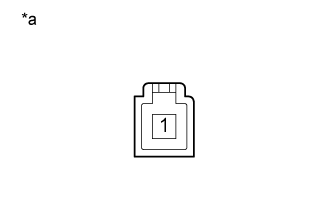
| 5.INSPECT PARKING BRAKE SWITCH |
Disconnect the E53 parking brake switch connector.
Measure the resistance according to the value(s) in the table below.
- Standard Resistance:
| Tester Connection | Switch Condition | Specified Condition |
| 1 - Body ground |
Parking brake applied
(Switch pin not pushed in) | Below 1 Ω |
Parking brake released
(Switch pin pushed in) | 10 kΩ or higher |
Text in Illustration | *a | Component without harness connected
(Parking Brake Switch) |
| | REPLACE PARKING BRAKE SWITCH ASSEMBLY ()
|
|
|
| 6.CHECK HARNESS AND CONNECTOR (PARKING BRAKE SWITCH - MAIN BODY ECU) |
Disconnect the E53 parking brake switch connector.
Disconnect the 2D main body ECU (cowl side junction block LH).
Measure the resistance according to the value(s) in the table below.
- Standard Resistance:
| Tester Connection | Condition | Specified Condition |
| E53-1 - 2D-22 | Always | Below 1 Ω |
| E53-1 - Body ground | Always | 10 kΩ or higher |
| | REPAIR OR REPLACE HARNESS OR CONNECTOR |
|
|
| OK | |
| |
| REPLACE MAIN BODY ECU (COWL SIDE JUNCTION BLOCK LH) |
|