Land Cruiser URJ200 URJ202 GRJ200 VDJ200 - PARK ASSIST / MONITORING
CHECK HARNESS AND CONNECTOR (PARKING ASSIST ECU - FRONT TELEVISION CAMERA ASSEMBLY AND BODY GROUND)
CHECK PARKING ASSIST ECU (BCB+, BGND)
CHECK FRONT TELEVISION CAMERA ASSEMBLY (BCV+, BGND)
DTC C1681 Front Camera Feedback Malfunction
DTC C1682 Front Camera Current Malfunction
DESCRIPTION
DTC C1681 is stored if the parking assist ECU judges as a result of its self check that a synchronization problem is occurring in the image signal sent from the front television camera assembly to the parking assist ECU.
DTC C1682 is stored if the parking assist ECU judges as a result of its self check that there is a problem with the current supplied from the front television camera assembly connected to the parking assist ECU.
| DTC Code | DTC Detection Condition | Trouble Area |
| C1681 | Front television camera power supply failure | Harness or connector Front television camera assembly Parking assist ECU |
| C1682 | An open or short in the front television camera signal circuit |
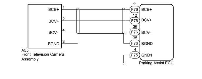
WIRING DIAGRAM
INSPECTION PROCEDURE
- NOTICE:
| 1.CHECK HARNESS AND CONNECTOR (PARKING ASSIST ECU - FRONT TELEVISION CAMERA ASSEMBLY AND BODY GROUND) |
Disconnect the F75 and F76 parking assist ECU connectors.
Disconnect the A55 front television camera assembly connector.
Measure the resistance according to the value(s) in the table below.
- Standard Resistance:
Tester Connection Condition Specified Condition F76-36 (BCV-) - A55-4 (BCV-) Always Below 1 Ω F76-12 (BCV+) - A55-2 (BCV+) Always Below 1 Ω F76-35 (BGND) - A55-3 (BGND) Always Below 1 Ω F76-11 (BCB+) - A55-1 (BCB+) Always Always F75-4 (GND1) - Body ground Always Always F76-36 (BCV-) - Body ground Always 10 kΩ or higher F76-12 (BCV+) - Body ground Always 10 kΩ or higher F76-35 (BGND) - Body ground Always 10 kΩ or higher F76-11 (BCB+) - Body ground Always 10 kΩ or higher
|
| ||||
| OK | |
| 2.CHECK PARKING ASSIST ECU (BCB+, BGND) |

Reconnect the F75 and F76 parking assist ECU connectors.
Measure the resistance according to the value(s) in the table below.
- Standard Resistance:
Tester Connection Condition Specified Condition F76-35 (BGND) - Body ground Always Below 1 Ω
Measure the voltage according to the value(s) in the table below.
- Standard Voltage:
Tester Connection Condition Specified Condition F76-11 (BCB+) - F76-35 (BGND) Engine switch on (IG), front and side monitor main switch assembly on 5.5 to 7.05 V
| *a | Component with harness connected (Parking Assist ECU) |
|
| ||||
| OK | |
| 3.CHECK FRONT TELEVISION CAMERA ASSEMBLY (BCV+, BGND) |
Reconnect the A55 front television camera assembly connector.
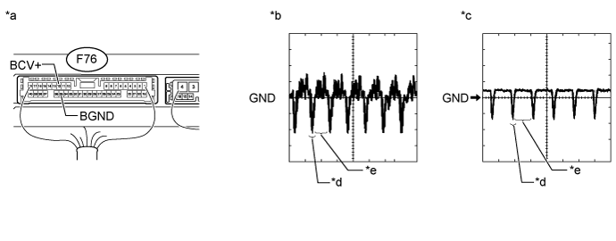
| *a | Component with harness connected (Parking Assist ECU) | *b | Waveform A |
| *c | Waveform B | *d | Synchronization Signal |
| *e | Video Waveform | - | - |
- HINT:
Measure the resistance according to the value(s) in the table below.
- OK:
- Waveform is as shown in the illustration.
| Item | Content |
| Terminal No. (Symbol) | F76-12 (BCV+) - F76-35 (BGND) |
| Tool Setting | 200 mV/DIV., 50 μsec./DIV. |
| Condition | Waveform A: Engine switch on (IG), front and side monitor main switch assembly on and camera lens is not covered, displaying an image Waveform B: Engine switch on (IG), front and side monitor main switch assembly on and camera lens is covered, blacking out the screen |
|
| ||||
| OK | ||
| ||