Land Cruiser URJ200 URJ202 GRJ200 VDJ200 - AUDIO / VIDEO
CHECK HARNESS AND CONNECTOR (RADIO RECEIVER - BATTERY AND BODY GROUND)
AUDIO AND VISUAL SYSTEM (w/o Stereo Component Amplifier) - Radio Receiver Power Source Circuit
DESCRIPTION
This circuit provides power to the radio receiver.
WIRING DIAGRAM
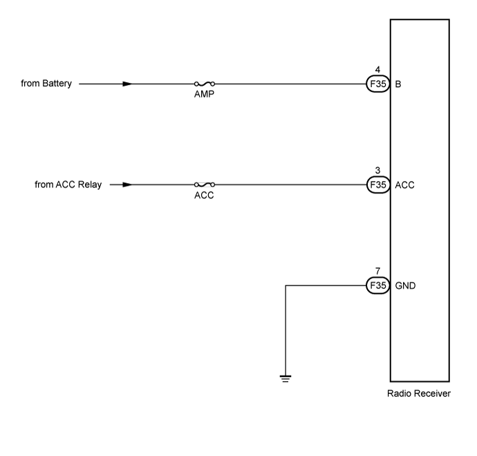
INSPECTION PROCEDURE
- NOTICE:
- Inspect the fuse for circuits related to this system before performing the following inspection procedure.
| 1.CHECK HARNESS AND CONNECTOR (RADIO RECEIVER - BATTERY AND BODY GROUND) |
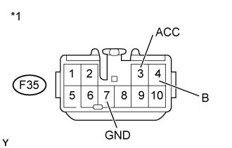
Disconnect the F35 receiver connector.
Measure the resistance according to the value(s) in the table below.
- Standard Resistance:
Tester Connection Condition Specified Condition F35-7 (GND) - Body ground Always Below 1 Ω
Measure the voltage according to the value(s) in the table below.
- Standard Voltage:
Tester Connection Condition Specified Condition F35-4 (B) - Body ground Always 11 to 14 V F35-3 (ACC) - Body ground Ignition switch ACC
| *1 | Front view of wire harness connector (to Radio Receiver) |
|
| ||||
| OK | ||
| ||