1. REMOVE OIL PRESSURE SENSOR
-
Using a 24 mm deep socket wrench, remove the oil pressure sensor.
2. REMOVE ENGINE COOLANT TEMPERATURE SENSOR
-
Remove the engine coolant temperature sensor and gasket.
3. DISCONNECT NO. 1 WATER BY-PASS PIPE (for Automatic Transmission)
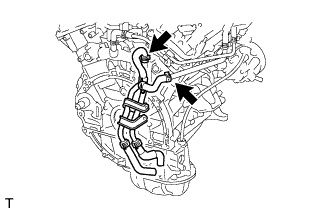
-
Disconnect the 2 water by-pass pipe hoses and remove the pipe.
4. DISCONNECT WATER HOSE SUB-ASSEMBLY (for Automatic Transmission)
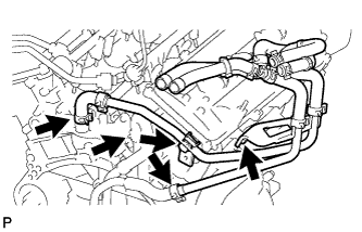
-
Remove the 2 bolts and disconnect the water hose.
5. DISCONNECT WATER HOSE SUB-ASSEMBLY (for Manual Transmission)

-
Remove the 2 bolts and disconnect the water hose.
6. REMOVE FUEL DELIVERY PIPE SUB-ASSEMBLY
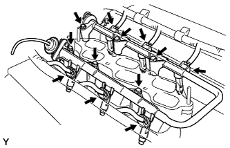
-
Disconnect the 6 fuel injector connectors.
-
Remove the 6 bolts and fuel delivery pipe together with the 6 fuel injectors.
NOTICE:
Be careful not to drop the injectors when removing the fuel delivery pipe.
7. REMOVE FUEL INJECTOR
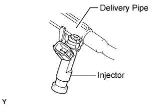
-
Pull the 6 fuel injectors from the fuel delivery pipe.
-
Remove the O-ring and injector vibration insulator from each fuel injector.
8. REMOVE INTAKE MANIFOLD
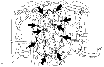
-
Remove the 10 bolts, intake manifold and 2 gaskets.
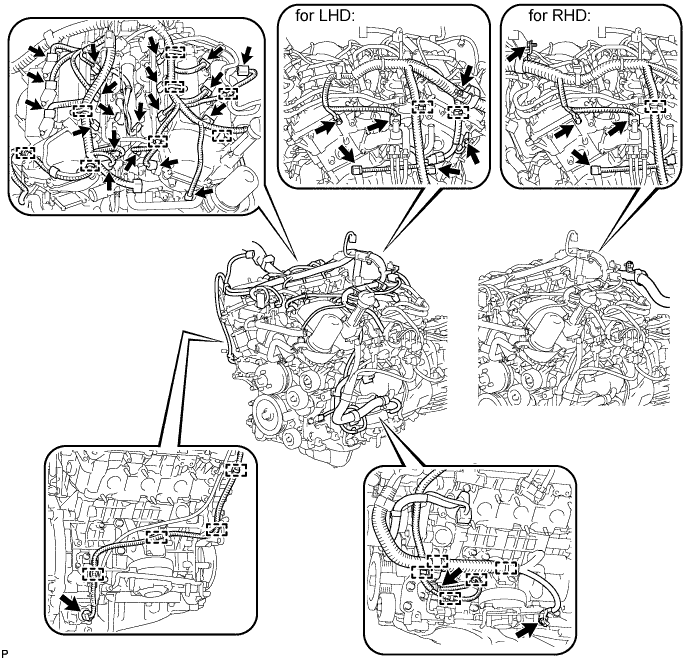
9. REMOVE ENGINE WIRE
10. REMOVE IGNITION COIL ASSEMBLY
-
Remove the 6 bolts and 6 ignition coils.
11. REMOVE V-RIBBED BELT TENSIONER ASSEMBLY

-
Remove the 5 bolts and V-ribbed belt tensioner.
12. REMOVE ENGINE OIL LEVEL DIPSTICK GUIDE
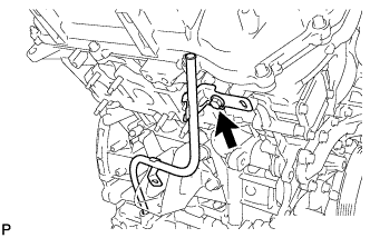
-
Remove the bolt and dipstick guide.
-
Remove the O-ring from the dipstick guide.
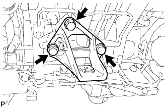
13. REMOVE FRONT NO. 1 ENGINE MOUNTING BRACKET RH
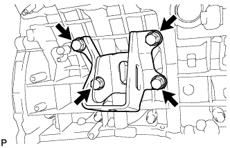
-
Remove the 4 bolts and front No. 1 engine mounting bracket RH.
14. REMOVE FRONT NO. 1 ENGINE MOUNTING BRACKET LH
-
Remove the 3 bolts and front No. 1 engine mounting bracket LH.
15. REMOVE NO. 1 IDLER PULLEY SUB-ASSEMBLY
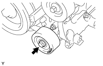
-
Remove the bolt and No. 1 idler pulley.
16. REMOVE NO. 2 IDLER PULLEY SUB-ASSEMBLY
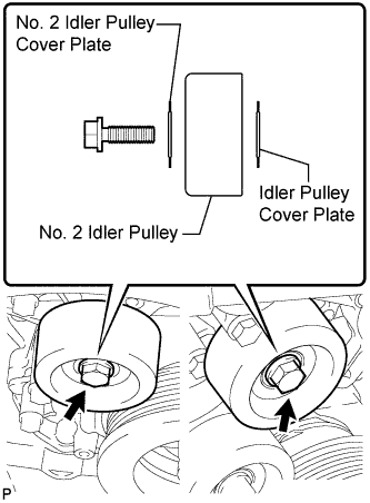
-
w/ Pulley Cover Plate: Remove the 2 bolts, 2 No. 2 idler pulley cover plate, 2 idler pulley and 2 idler pulley cover plate.

-
w/o Pulley Cover Plate: Remove the 2 bolts and 2 No. 2 idler pulleys.
17. REMOVE FLYWHEEL RING GEAR (for Manual Transmission)
HINT:
If the flywheel ring gear is deformed or the gears are damaged, replace it.
CAUTION:
Wear protective gloves. Hot ares on the flywheel ring gear may injure your hands.
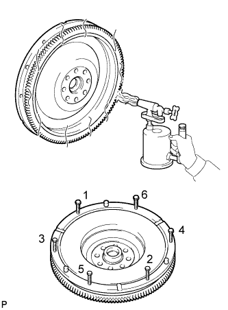
-
Using a torch, heat the ring gear evenly to approximately 200°C (392°F).
-
Temporarily install 6 bolts (8 mm x 1.25 pitch) with a length of 70 mm or more to the flywheel.
-
Uniformly tighten the 6 bolts in the order shown in the illustration.
-
Remove the ring gear from the flywheel.