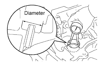
1. INSPECT CYLINDER HEAD SET BOLT
-
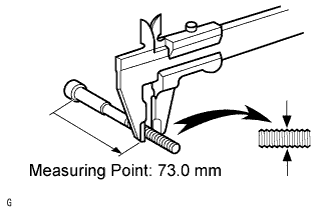
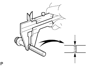
Using a vernier caliper, measure the outside thread diameter of the bolt.
Measuring point:
73.0 mm (2.87 in.)
Standard outside diameter:
10.85 to 11.0 mm (0.427 to 0.433 in.)
Minimum outside diameter:
10.7 mm (0.421 in.)
HINT:
If a visual check reveals no excessively thin areas, check the center of the bolt (see illustration) and find the area that has the smallest diameter.
If the diameter is less than the minimum, replace the cylinder head bolt.
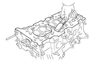
2. CLEAN CYLINDER HEAD SUB-ASSEMBLY
-
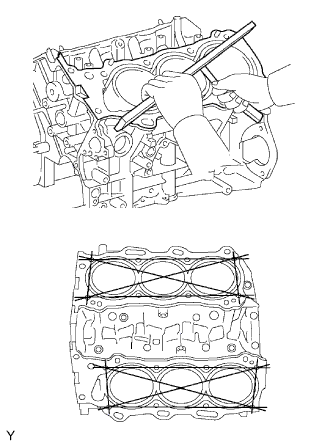
Using a gasket scraper, remove all the gasket material from the cylinder block contact surface.
NOTICE:
Be careful not to scratch the cylinder block contact surface.
-
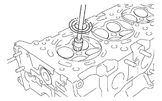
Using a wire brush, remove all the carbon from the combustion chambers.
NOTICE:
Be careful not to scratch the combustion chambers.

-
Using a valve guide bushing brush and solvent, clean all the valve guide bushes.
-
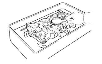
Using a soft brush and solvent, thoroughly clean the cylinder head.
3. INSPECT CYLINDER HEAD SUB-ASSEMBLY
-
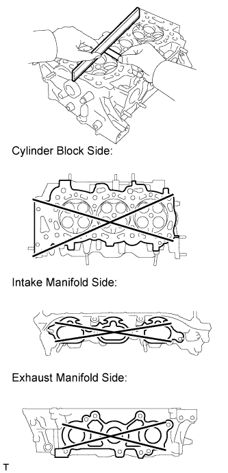
Using a precision straightedge and feeler gauge, measure the warpage of the contact surfaces of the cylinder block and manifolds.
Standard Warpage:
Item Specified Condition Cylinder block side 0.05 mm (0.00197 in.) Intake manifold side 0.08 mm (0.00315 in.) Exhaust manifold side 0.08 mm (0.00315 in.) Maximum Warpage:
If the warpage is more than the maximum, replace the cylinder head sub-assembly.Item Specified Condition Cylinder block side 0.10 mm (0.00394 in.) Intake manifold side 0.10 mm (0.00394 in.) Exhaust manifold side 0.10 mm (0.00394 in.)

-
Using a dye penetrant, check the intake ports, exhaust ports and cylinder surface for cracks. If there are cracks, replace the cylinder head sub-assembly.
4. CLEAN VALVE

-
Using a gasket scraper, chip off any carbon from the valve head.
-
Using a wire brush, thoroughly clean the valve.
5. INSPECT VALVE
-
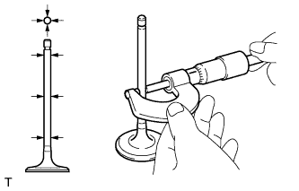
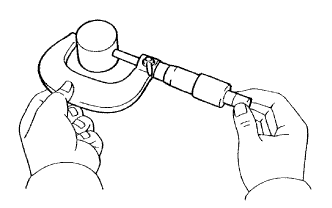
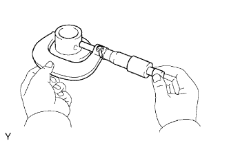
Using a micrometer, measure the diameter of the valve stem.
Standard Valve Stem Diameter:
Item Specified Condition Intake 5.470 to 5.485 mm (0.2154 to 0.2159 in.) Exhaust 5.465 to 5.480 mm (0.2152 to 0.2156 in.)

-
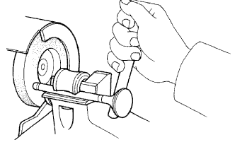
Inspect the valve face angle.
-
Grind the valve enough to remove pits and carbon.
-
Check that the valve is ground to the correct valve face angle.
Standard valve face angle:
44.5°
-

-
Using a vernier caliper, measure the valve head margin thickness.
-
Using a vernier caliper, check the valve head margin thickness.
Standard margin thickness:
1.0 mm (0.0394 in.)
Minimum margin thickness:
0.5 mm (0.0197 in.)
If the margin thickness is less than the minimum, replace the valve.
-

-
Using a vernier caliper, measure the overall length of the valve.
-
Using a vernier caliper, check the overall length.
Standard Overall Length:
Item Specified Condition Intake 106.95 mm (4.21 in.) Exhaust 105.80 mm (4.15 in.) Minimum Overall Length:
If the overall length is less than the minimum, replace the valve.Item Specified Condition Intake 106.40 mm (4.19 in.) Exhaust 105.30 mm (4.15 in.)
-
-
Inspect the valve stem tip.
-
Check the surface of the valve stem tip for wear.
NOTICE:
Do not grind the valve so it becomes shorter than the minimum overall length.
If the valve stem tip is worn, resurface the tip with a grinder or replace the valve.
-
6. CLEAN VALVE SEAT
-
Using a 45° carbide cutter, resurface the valve seats.
-
Clean the valve seats.
7. INSPECT VALVE SEAT
-
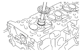
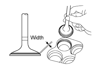
Apply a light coat of Prussian blue to the valve face.
-
Lightly press the valve face against the valve seat.
NOTICE:
Do not rotate the valve.
-
Check the valve face and valve seat by using the following procedure.
-
If Prussian blue appears around the entire valve face, the valve face is concentric. If not, replace the valve.
-
If Prussian blue appears around the entire valve seat, the guide and valve face are concentric. If not, resurface the valve seat.
-
Check that the seat contacts the middle of the valve face with the width below.
Standard width:
1.0 to 1.4 mm (0.0394 to 0.0551 in.)
-
8. INSPECT INNER COMPRESSION SPRING

-
Using a steel square, measure the deviation of the inner compression spring.
Maximum deviation:
2.0 mm (0.0787 in.)
If the deviation is more than the maximum, replace the inner compression spring.
-
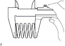
Using a vernier caliper, measure the free length of the inner compression spring.
Standard free length:
47.80 mm (1.88 in.)
If the free length is not as specified, replace the inner compression spring.
-
Using a spring tester, measure the tension of the inner compression spring at the standard installed length.
Standard installed tension:
186 to 206 N (19 to 21 kgf, 42 to 46 lbf) at 33.3 mm (1.31 in.)
If the installed tension is not as specified, replace the inner compression spring.
9. INSPECT VALVE GUIDE BUSH OIL CLEARANCE

-
Using a caliper gauge, measure the inside diameter of the guide bush.
Standard bush inside diameter:
5.51 to 5.53 mm (0.217 to 0.218 in.)
-
Subtract the valve stem diameter measurement from the guide bush inside diameter measurement.
Standard Oil Clearance:
Item Specified Condition Intake 0.025 to 0.060 mm (0.000984 to 0.00236 in.) Exhaust 0.030 to 0.065 mm (0.00118 to 0.00256 in.) Maximum Oil Clearance:
If the oil clearance is more than the maximum, replace the valve and valve guide bush.Item Specified Condition Intake 0.08 mm (0.00315 in.) Exhaust 0.10 mm (0.00394 in.)
10. INSPECT VALVE LIFTER
-
Using a micrometer, measure the valve lifter diameter.
Standard valve lifter diameter:
30.966 to 30.976 mm (1.219 to 1.220 in.)
If the result is not as specified, replace the valve lifter.
11. INSPECT VALVE LIFTER OIL CLEARANCE
-
Using a caliper gauge, measure the lifter bore diameter of the cylinder head.
Standard lifter bore diameter:
31.009 to 31.025 mm (1.220 to 1.221 in.)
-
Subtract the valve lifter diameter measurement (see "Inspect Valve Lifter" procedure) from the lifter bore diameter measurement.
Standard oil clearance:
0.033 to 0.059 mm (0.00130 to 0.00232 in.)
Maximum oil clearance:
0.08 mm (0.00315 in.)
If the oil clearance is more than the maximum, replace the valve lifter. If necessary, replace the cylinder head.
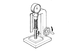
12. INSPECT CAMSHAFT THRUST CLEARANCE

-
Install the camshafts.
-
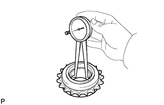
Using a dial indicator, measure the thrust clearance while moving the camshaft back and forth.
Standard thrust clearance:
0.04 to 0.09 mm (0.00157 to 0.00354 in.)
Maximum thrust clearance:
0.11 mm (0.00433 in.)
If the thrust clearance is more than the maximum, replace the camshafts. If necessary, replace the camshaft bearing caps and cylinder head as a set.
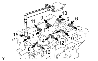
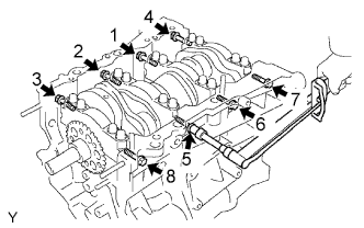
13. INSPECT CAMSHAFT OIL CLEARANCE
-
Clean the camshaft bearing caps, camshaft bearings and camshaft journals.
-
Install the camshaft bearing.
-
Place the camshafts on the cylinder head.
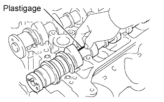
-
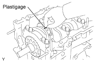
Lay a strip of Plastigage across each of the camshaft journals.
-
Install the camshaft bearing caps.
NOTICE:
Do not turn the camshafts.
-
Remove the camshaft bearing caps.
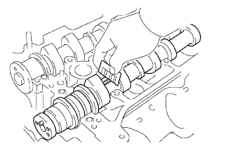
-
Measure the Plastigage at its widest point.
Standard Oil Clearance (for Cylinder Head RH):
Item Specified Condition No. 1 (Intake) 0.008 to 0.038 mm (0.000315 to 0.00150 in.) No. 1 (Exhaust) 0.040 to 0.079 mm (0.00157 to 0.00311 in.) Others 0.025 to 0.062 mm (0.000984 to 0.00244 in.) Standard Oil Clearance (for Cylinder Head LH):
Item Specified Condition No. 1 0.040 to 0.079 mm (0.00157 to 0.00311 in.) Others 0.025 to 0.062 mm (0.000984 to 0.00244 in.) Maximum Oil Clearance (for Cylinder Head RH):
Item Specified Condition No. 1 (Intake) 0.07 mm (0.00276 in.) Others 0.10 mm (0.00394 in.) Maximum Oil Clearance (for Cylinder Head LH):
If the oil clearance is more than the maximum, replace the camshaft bearings and/or camshaft. If necessary, replace the camshaft bearing caps and cylinder head together.Item Specified Condition - 0.10 mm (0.00394 in.) Reference:
Item Specified Condition Cylinder head journal bore diameter 40.009 to 40.017 mm (1.5752 to 1.5755 in.) Camshaft bearing center wall thickness (Mark "2") 2.004 to 2.008 mm (0.0789 to 0.0791 in.) Camshaft journal diameter 35.971 to 35.985 mm (1.4162 to 1.4167 in.)
-
Remove the Plastigage completely.
-
Remove the camshafts.
-
Remove the camshaft bearing.
14. INSPECT CAMSHAFT

-
Inspect the camshaft runout.
-
Place the camshaft on V-blocks.
-
Using a dial indicator, measure the runout at the center journal.
Maximum runout:
0.06 mm (0.00236 in.)
If the runout is more than the maximum, replace the camshaft.
-

-
Inspect the cam lobes.
-
Using a micrometer, measure the cam lobe height.
Standard Cam Lobe Height:
Item Specified Condition Intake 44.168 to 44.268 mm (1.739 to 1.742 in.) Exhaust 44.580 to 44.680 mm (1.755 to 1.759 in. Minimum Cam Lobe Height:
If the cam lobe height is less than the minimum, replace the camshaft.Item Specified Condition Intake 44.018 mm (1.73 in.) Exhaust 44.430 mm (1.75 in.) 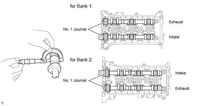
-
-
Inspect the camshaft journals.
-
Using a micrometer, measure the journal diameter.
Standard Journal Diameter:
If the journal diameter is not as specified, check the oil clearance.Item Specified Condition No. 1 35.971 to 35.985 mm (1.416 to 1.417 in.) Other 22.959 to 22.975 mm (0.904 to 0.905 in.)
-
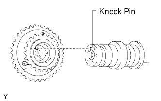
15. INSPECT CAMSHAFT TIMING GEAR ASSEMBLY
-
Fix the intake camshaft with a vise.
NOTICE:
Be careful not to damage the camshaft.
-
Align the knock pin hole in the camshaft timing gear with the knock pin of the camshaft, and install the camshaft timing gear with the bolt.
Torque:
100 N*m{ 1020 kgf*cm , 74 ft.*lbf }
-
Confirm the camshaft timing gear is locked.
-
Release the lock pin.
-
Cover the 4 oil paths of the cam journal with vinyl tape as shown in the illustration.
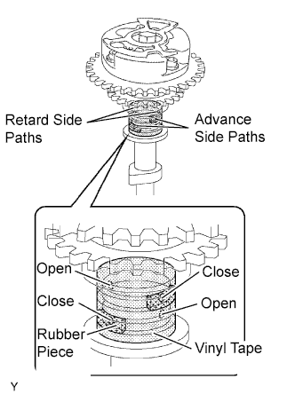
HINT:
One of the 2 grooves on the cam journal is for retard side paths (upper) and the other is for advance side paths (lower). Each groove has 2 oil paths. Plug one of the oil paths for each groove with rubber pieces as shown in the illustration before wrapping the cam journal with tape.
-
Prink a hole in the tape at the 2 oil holes not plugged with rubber pieces.
-
Apply about 200 kPa (2.0 kgf/cm2, 28 psi) of air pressure to the two broken paths (the advance side path and the retard side path).

NOTICE:
Cover the paths with a cloth to avoid oil splashing.
-
Confirm that the camshaft timing gear rotates in the advance direction when reducing the air pressure applied to the retard path.
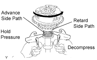
HINT:
When the lock pin is released, the camshaft timing gear rotates in the advance direction.
-
When the camshaft timing gear comes to the most advanced position, release the air pressure from the retard side path, and then release the air pressure from the advance side path.
NOTICE:
The camshaft timing gear occasionally shifts to the retard side abruptly if air compression of the advanced side path is released first. This often results in the breakage of the lock pin.
-
-
Check for smooth rotation.
-
Except the position where the lock pin meets at the most retarded angle, turn the camshaft timing gear back and forth and check the movable range and that there is no disturbance.
Standard:
Movable smoothly in the range of about 31°
NOTICE:
Be sure to perform this check by hand, instead of with air pressure.
-
-
Check the lock in the most retarded position.
-
Confirm that the camshaft timing gear is locked at the most retarded position.
-
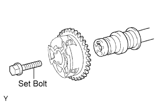
-
Remove the set bolt and camshaft timing gear.
NOTICE:
Be sure not to remove the other 3 bolts.
16. INSPECT CONNECTING ROD BOLT

-
Using a vernier caliper, measure the tension portion diameter of the bolt.
Standard diameter:
7.2 to 7.3 mm (0.283 to 0.287 in.)
Minimum diameter:
7.0 mm (0.276 in.)
If the diameter is less than the minimum, replace the connecting rod bolt.
17. INSPECT CRANKSHAFT BEARING CAP SET BOLT
-
Using a vernier caliper, measure the tension portion diameter of the bolt.
Standard diameter:
10.0 to 10.2 mm (0.394 to 0.402 in.)
If the diameter is less than the minimum, replace the crankshaft bearing cap set bolt.
18. INSPECT CYLINDER BLOCK FOR FLATNESS
-
Using a precision straightedge and feeler gauge, measure the warpage of the contact surface of the cylinder head gasket.
Maximum warpage:
0.05 mm (0.00197 in.)
If the warpage is more than the maximum, replace the cylinder block.
19. INSPECT CYLINDER BORE

-
Using a cylinder gauge, measure the cylinder bore diameter at positions A and B in the thrust and axial directions.
Standard diameter:
94.000 to 94.012 mm (3.7008 to 3.7013 in.)
Maximum diameter:
94.132 mm (3.7060 in.)
If the diameter is more than the maximum, replace the cylinder block.
20. INSPECT PISTON WITH PIN SUB-ASSEMBLY
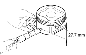
-
Using a micrometer, measure the piston diameter at a right angle to the piston pin center line, 27.7 mm (1.091 in.) from the piston head.
Piston diameter:
93.910 to 93.920 mm (3.6972 to 3.6976 in.)
21. INSPECT PISTON OIL CLEARANCE
-
Subtract the piston diameter measurement from the cylinder bore diameter measurement.
Standard oil clearance:
0.080 to 0.102 mm (0.00315 to 0.00401 in.)
Maximum oil clearance:
0.13 mm (0.00512 in.)
If the oil clearance is more than the maximum, replace all 6 pistons. If necessary, replace the cylinder block.
22. INSPECT PISTON PIN OIL CLEARANCE

-
Check each mark on the piston and connecting rod.
-
Using a caliper gauge, measure the inside diameter of the piston pin hole.
Standard Piston Pin Hole Inside Diameter:
Mark Specified Condition A 22.001 to 22.004 mm (0.86618 to 0.86630 in.) B 22.005 to 22.007 mm (0.86634 to 0.86642 in.) C 22.008 to 22.010 mm (0.86645 to 0.86653 in.)

-
Using a micrometer, measure the piston pin diameter.
Standard Piston Pin Diameter:
Mark Specified Condition A 21.997 to 22.000 mm (0.86602 to 0.86614 in.) B 22.001 to 22.003 mm (0.86618 to 0.86626 in.) C 22.004 to 22.006 mm (0.86630 to 0.86642 in.)
-
Using a caliper gauge, measure the inside diameter of the connecting rod bush.
Standard Bush Inside Diameter:
Mark Specified Condition A 22.005 to 22.008 mm (0.86634 to 0.86645 in.) B 22.009 to 22.011 mm (0.86649 to 0.86657 in.) C 22.012 to 22.014 mm (0.86661 to 0.86669 in.)
-
Subtract the piston pin diameter measurement from the piston pin hole diameter measurement.
Standard oil clearance:
0.001 to 0.007 mm (0.0000394 to 0.000276 in.)
Maximum oil clearance:
0.040 mm (0.00157 in.)
If the oil clearance is more than the maximum, replace the piston and piston pin as a set.
-
Subtract the piston pin diameter measurement from the bush inside diameter measurement.
Standard oil clearance:
0.005 to 0.011 mm (0.000197 to 0.000433 in.)
Maximum oil clearance:
0.050 mm (0.00197 in.)
If the oil clearance is more than the maximum, replace the bush. If necessary, replace the connecting rod and piston pin as a set.
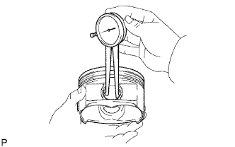
23. INSPECT RING GROOVE CLEARANCE

-
Using a feeler gauge, measure the clearance between a new piston ring and the wall of the ring groove.
Standard Ring Groove Clearance:
If the clearance is not as specified, replace the piston with pin sub-assembly.Item Specified Condition No. 1 Compression Ring 0.02 to 0.07 mm (0.000787 to 0.00276 in.) No. 2 Compression Ring 0.02 to 0.06 mm (0.000787 to 0.00236 in.) Oil Ring 0.07 to 0.15 mm (0.00276 to 0.00590 in.)
24. INSPECT PISTON RING END GAP
-
Insert the piston ring into the cylinder bore.
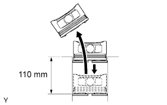
-
Using a piston, push the piston ring a little beyond the bottom of the ring travel, 110 mm (4.33 in.) from the top of the cylinder block.

-
Using a feeler gauge, measure the end gap.
Standard End Gap:
Item Specified Condition No. 1 Compression Ring 0.30 to 0.40 mm (0.0118 to 0.0157 in.) No. 2 Compression Ring 0.40 to 0.50 mm (0.0157 to 0.0197 in.) Oil Ring (side rail) 0.10 to 0.40 mm (0.00394 to 0.0157 in.) Maximum End Gap:
If the end gap is more than the maximum, replace the piston ring. If the end gap is more than the maximum even with a new piston ring, rebore all 6 cylinders or replace the cylinder block sub-assembly.Item Specified Condition No. 1 Compression Ring 1.0 mm (0.0394 in.) No. 2 Compression Ring 1.1 mm (0.0433 in.) Oil Ring (side rail) 1.0 mm (0.0394 in.)
25. INSPECT CONNECTING ROD SUB-ASSEMBLY
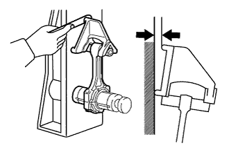
-
Using a rod aligner and feeler gauge, check the connecting rod alignment.
-
Check for bend.
Maximum bend:
0.05 mm (0.00197 in.) per 100 mm (3.94 in.)
If the bend is more than the maximum, replace the connecting rod sub-assembly. -
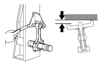
Check for twist.
Maximum twist:
0.15 mm (0.00591 in.) per 100 mm (3.94 in.)
If the twist is more than the maximum, replace the connecting rod sub-assembly.
-
26. INSPECT CRANKSHAFT
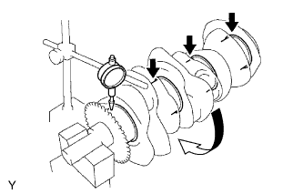
-
Using a dial indicator and V-blocks, measure the runout as shown in the illustration.
Maximum circle runout:
0.06 mm (0.00236 in.)
If the circle runout is more than the maximum, replace the crankshaft.

-
Using a micrometer, measure the diameter of each main journal.
Standard diameter:
71.988 to 72.000 mm (2.8342 to 2.8346 in.)
If the diameter is not as specified, check the oil clearance. If necessary, replace the crankshaft.
-
Check each main journal for taper and out-of-round as shown in the illustration.
Maximum taper and out-of-round:
0.02 mm (0.000787 in.)
If the taper and out-of-round is more than the maximum, replace the crankshaft.
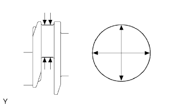
-
Using a micrometer, measure the diameter of each crank pin.
Standard diameter:
55.992 to 56.000 mm (2.2044 to 2.2047 in.)
If the diameter is not as specified, check the oil clearance. If necessary, replace the crankshaft.
-
Check each crank pin for taper and out-of-round as shown in the illustration.
Maximum taper and out-of-round:
0.02 mm (0.000787 in.)
If the taper and out-of-round is more than the maximum, replace the crankshaft.
27. INSPECT CRANKSHAFT THRUST CLEARANCE
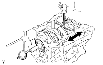
-
Using a dial indicator, measure the thrust clearance while prying the crankshaft back and forth with a screwdriver.
Standard thrust clearance:
0.04 to 0.24 mm (0.00157 to 0.00945 in.)
Maximum thrust clearance:
0.30 mm (0.0118 in.)
If the thrust clearance is more than the maximum, replace the thrust washers as a set.Standard thrust washer thickness:
1.93 to 1.98 mm (0.0760 to 0.0780 in.)
If necessary, replace the crankshaft.
28. INSPECT CRANKSHAFT OIL CLEARANCE
HINT:
Main bearings come in widths of 19.0 mm (0.748 in.) and 22.4 mm (0.882 in.). Install the 22.4 mm (0.882 in.) bearings in the No. 1 and No. 4 cylinder block journal positions with the main bearing caps. Install the 19.0 mm (0.748 in.) bearings in the No. 2 and No. 3 positions.
-
Clean each main journal and bearing.

-
Align the bearing claw with the claw groove of the cylinder block, and push in the 4 upper bearings.
NOTICE:
- Do not apply engine oil to the bearings and contact surfaces.
- Do not allow coolant to come into contact with the bearing inner surface.
- If any coolant comes into contact with the bearing inner surface, replace the bearing with a new one.
-
Align the bearing claw with the claw groove of the main bearing cap, and push in the 4 lower bearings.
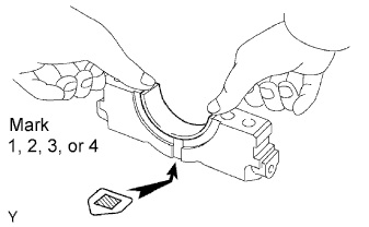
NOTICE:
- Do not apply engine oil to the bearings and contact surfaces.
- Do not allow coolant to come into contact with the bearing inner surface.
- If any coolant comes into contact with the bearing inner surface, replace the bearing with a new one.
HINT:
A number marked on each main bearing cap indicates the installation position.
-
Place the crankshaft on the cylinder block.
-
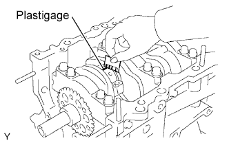
Lay a strip of Plastigage across each journal.

-
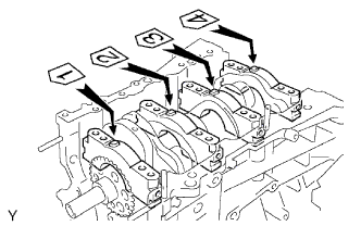
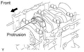
Examine the front marks and numbers and set the crankshaft bearing caps on the cylinder block.
-
Apply a light coat of engine oil to the threads of the crankshaft bearing cap bolts.
-
Temporarily install the 8 crankshaft bearing cap bolts to the inside positions.
-
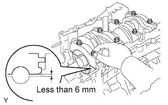
Tighten the 2 bolts for each bearing cap until the clearance between the crankshaft bearing cap and the cylinder block becomes less than 6 mm (0.236 in.).
-
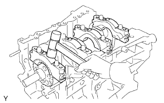
Using a plastic-faced hammer, lightly tap the crankshaft bearing cap to ensure a proper fit.
-
Apply a light coat of engine oil to the threads of the crankshaft bearing bolts and temporarily install the 8 crankshaft bearing cap bolts to the outside positions.

-
Step 1:
-
Uniformly tighten the 16 bolts in several steps in the order shown in the illustration.
Torque:
61 N*m{ 622 kgf*cm , 45 ft.*lbf }
-
-
Step 2:
-
Mark the front side of the crankshaft bearing cap bolts with paint.

-
Tighten the bearing cap bolts 90° in the order shown in step 1.
-
-
Check that the painted marks are now at a 90° angle to the front.
NOTICE:
Do not turn the crankshaft.
-
Install and uniformly tighten the 8 crankshaft bearing cap bolts in several steps in the sequence shown in the illustration.
Torque:
26 N*m{ 262 kgf*cm , 19 ft.*lbf }
-
Remove the crankshaft bearing caps.
-
Step 1: Uniformly loosen and remove the 8 bearing cap bolts in the sequence shown in the illustration.

-
Step 2: Uniformly loosen and remove the 16 bearing cap bolts in the sequence shown in the illustration.

-
-
Measure the Plastigage at its widest point.

Standard oil clearance:
0.018 to 0.030 mm (0.000709 to 0.00118 in.)
Maximum clearance:
0.046 mm (0.00181 in.)
If the oil clearance is more than the maximum, replace the bearings. If necessary, replace the crankshaft.NOTICE:
Completely remove the Plastigage.
-
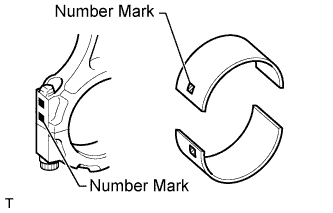
If replacing a bearing, replace it with one that has the same number. If the number of the bearing cannot be determined, select the correct bearing by adding together the numbers imprinted on the cylinder block and crankshaft, then refer to the table below for the appropriate bearing number. There are 5 sizes of standard bearings, marked "1", "2", "3", "4" and "5" accordingly.

Journal Bearings:
Cylinder block (A) + Crankshaft (B) Use Bearing 0 - 5 "1" 6 - 11 "2" 12 - 17 "3" 18 - 23 "4" 24 - 28 "5" HINT:
Example:
Cylinder block "11" (A) + Crankshaft "06" (B) = Total number 17 (Use bearing "3")
Standard Journal Diameter:
Item Mark Specified Condition Cylinder block main journal bore diameter (A) "00" 77.000 mm (3.03149 in.) "01" 77.001 mm (3.03152 in.) "02" 77.002 mm (3.03156 in.) "03" 77.003 mm (3.03160 in.) "04" 77.004 mm (3.03164 in.) "05" 77.005 mm (3.03168 in.) "06" 77.006 mm (3.03172 in.) "07" 77.007 mm (3.03176 in.) "08" 77.008 mm (3.03180 in.) "09" 77.009 mm (3.03184 in.) "10" 77.010 mm (3.03188 in.) "11" 77.011 mm (3.03192 in.) "12" 77.012 mm (3.0396 in.) "13" 77.013 mm (3.03200 in.) "14" 77.014 mm (3.03204 in.) "15" 77.015 mm (3.03208 in.) "16" 77.016 mm (3.03211 in.) Crankshaft main journal diameter (B) "00" 71.999 to 72.000 mm (2.83460 to 2.83464 in.) "01" 71.998 to 71.999 mm (2.83456 to 2.83460 in.) "02" 71.997 to 71.998 mm (2.83452 to 2.83456 in.) "03" 71.996 to 71.997 mm (2.83448 to 2.83452 in.) "04" 71.995 to 71.996 mm (2.83440 to 2.83448 in.) "05" 71.994 to 71.995 mm (2.83440 to 2.83444 in.) "06" 71.993 to 71.994 mm (2.83436 to 2.83440 in.) "07" 71.992 to 71.993 mm (2.83432 to 2.83436 in.) "08" 71.991 to 71.992 mm (2.83428 to 2.83432 in.) "09" 71.990 to 71.991 mm (2.83424 to 2.83428 in.) "10" 71.989 to 71.990 mm (2.83420 to 2.83424 in.) "11" 71.988 to 71.989 mm (2.83416 to 2.83420 in.) Standard Bearing Center Wall Thickness:
Mark Specified Condition "1" 2.488 to 2.491 mm (0.0980 to 0.0981 in.) "2" 2.491 to 2.494 mm (0.0981 to 0.0982 in.) "3" 2.494 to 2.497 mm (0.0982 to 0.0983 in.) "4" 2.497 to 2.500 mm (0.0983 to 0.0984 in.) "5" 2.500 to 2.503 mm (0.0984 to 0.0985 in.)
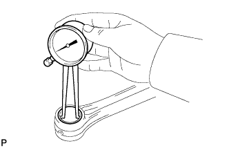
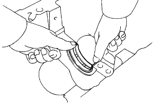
29. INSPECT CONNECTING ROD THRUST CLEARANCE
-
Using a dial indicator, measure the thrust clearance while moving the connecting rod back and forth.
Standard thrust clearance:
0.15 to 0.30 mm (0.00591 to 0.0118 in.)
Maximum thrust clearance:
0.35 mm (0.0138 in.)
If the thrust clearance is more than the maximum, replace one or more connecting rods as necessary. If necessary, replace the crankshaft.
30. INSPECT CONNECTING ROD OIL CLEARANCE
-
Install the crankshaft bearing.
-
Install the crankshaft.
-
Lay a strip of Plastigage across the crank pin.
-
Set the connecting rod cap so that the protrusion is facing the correct direction.
-
Apply a light coat of engine oil to the threads of the connecting rod cap bolts.

-
Step 1:
-
Install and alternately tighten the bolts of the connecting rod cap in several steps.
Torque:
25 N*m{ 250 kgf*cm , 18 ft.*lbf }
-
-
Step 2:
-
Mark the front side of each connecting rod cap bolt with paint.
-
Tighten the bearing cap bolts in step 1 90°.
-
-
Remove the 2 bolts, connecting rod cap and lower bearing.
-
Measure the Plastigage at its widest point.
Standard oil clearance:
0.026 to 0.046 mm (0.00102 to 0.00181 in.)
Maximum oil clearance:
0.066 mm (0.00260 in.)
If the oil clearance is more than the maximum, replace the bearings. If necessary, replace the crankshaft.NOTICE:
Completely remove the Plastigage.
-
If replacing a bearing, replace it with one that has the same number marked on the connecting rod. There are 4 sizes of standard bearings, marked "1 ", "2", "3" and "4" accordingly.
Standard Bearing Center Wall Thickness:
Mark Specified Condition 1 1.484 to 1.487 mm (0.05843 to 0.05854 in.) 2 1.487 to 1.490 mm (0.05854 to 0.05866 in.) 3 1.490 to 1.493 mm (0.05866 to 0.05878 in.) 4 1.493 to 1.496 mm (0.05878 to 0.05900 in.)
-
Remove the crankshaft.
-
Remove the crankshaft bearing.
31. INSPECT NO. 1 CHAIN SUB-ASSEMBLY

-
Using a spring scale, pull the No. 1 chain with a force of 147 N (15 kgf, 33.1 lbf) and measure the length of the No. 1 chain by using a vernier caliper.
Maximum chain elongation:
146.8 mm (5.78 in.)
HINT:
Perform the measurement at 3 random places.
If a measurement is more than the maximum, replace the No. 1 chain.
32. INSPECT NO. 2 CHAIN SUB-ASSEMBLY
-
Using a spring scale, pull the No. 2 chain with a force of 147 N (15 kgf, 33.1 lbf) and measure the length of the No. 2 chain by using a vernier caliper.
Maximum chain elongation:
146.8 mm (5.78 in.)
HINT:
Perform the measurement at 3 random places.
If a measurement is more than the maximum, replace the No. 2 chain.
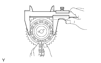
33. INSPECT CAMSHAFT TIMING GEAR ASSEMBLY
-
Wrap the No. 1 chain around the gear place for the No. 1 chain.
-
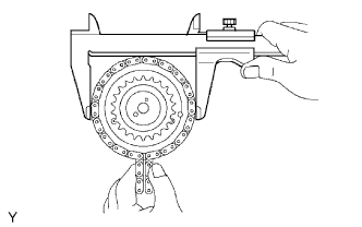
Using a vernier caliper, measure the timing gear with the No. 1 chain.
Minimum gear diameter (with chain):
115.5 mm (4.55 in.)
HINT:
The vernier caliper must contact the chain rollers for the measurement.
If the diameter is less than the minimum, replace the No. 1 chain and camshaft timing gear assembly.
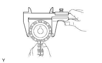
-
Wrap the No. 2 chain around the gear place for the No. 2 chain.
-
Using a vernier caliper, measure the timing gear with the No. 2 chain.
Minimum gear diameter (with chain):
73.1 mm (2.88 in.)
HINT:
The vernier caliper must contact the chain rollers for the measurement.
If the diameter is less than the minimum, replace the No. 2 chain and camshaft timing gear assembly.
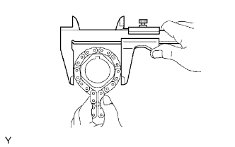
34. INSPECT CAMSHAFT TIMING SPROCKET
-
Wrap the No. 2 chain around the sprocket.
-
Using a vernier caliper, measure the camshaft timing sprocket diameter with the No. 2 chain.
Minimum gear diameter (with chain):
73.1 mm (2.88 in.)
HINT:
The vernier caliper must contact the chain rollers for the measurement.
If the diameter is less than the minimum, replace the No. 2 chain and camshaft timing sprocket.
35. INSPECT CRANKSHAFT TIMING SPROCKET
-
Wrap the No. 1 chain around the sprocket.
-
Using a vernier caliper, measure the crankshaft timing sprocket diameter with the No. 1 chain.
Minimum gear diameter (with chain):
61.0 mm (2.40 in.)
HINT:
The vernier caliper must contact the chain rollers for the measurement.
If the diameter is less than the minimum, replace the No. 1 chain and crankshaft timing sprocket.
36. INSPECT NO. 1 IDLE GEAR
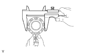
-
Wrap the No. 1 chain around the gear.
-
Using a vernier caliper, measure the No. 1 idle gear with the No. 1 chain.
Minimum gear diameter (with chain):
61.0 mm (2.40 in.)
HINT:
The vernier caliper must contact the chain rollers for the measurement.
If the diameter is less than the minimum, replace the No. 1 chain and No. 1 idle gear.
37. INSPECT NO. 1 IDLE GEAR SHAFT OIL CLEARANCE
-
Using a micrometer, measure the No. 1 idle gear shaft diameter.
Standard idle gear shaft diameter:
22.987 to 23.000 mm (0.905 to 0.906 in.)
-
Using a caliper gauge, measure the inside diameter of the idle gear.
Standard idle gear inside diameter:
23.02 to 23.03 mm (0.906 to 0.907 in.)
-
Subtract the idle gear shaft diameter measurement from the idle gear inside diameter measurement.
Standard oil clearance:
0.020 to 0.043 mm (0.000787 to 0.00169 in.)
Maximum oil clearance:
0.093 mm (0.00366 in.)
If the thrust oil clearance is more than the maximum, replace the idle gear shaft and idle gear.
38. INSPECT NO. 1 CHAIN TENSIONER ASSEMBLY
-
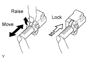
Move the stopper plate upward to release the lock. Push the plunger and check that it moves smoothly. If necessary, replace the chain tensioner assembly.
39. INSPECT NO. 2 CHAIN TENSIONER ASSEMBLY
-
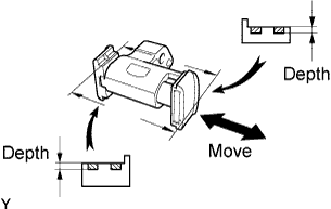
Check that the plunger moves smoothly.
-
Measure the worn depth of the chain tensioner.
Maximum depth:
1.0 mm (0.0394 in.)
If the depth is more than the maximum, replace the No. 2 chain tensioner assembly.
40. INSPECT NO. 3 CHAIN TENSIONER ASSEMBLY
-
Check that the plunger moves smoothly.
-
Measure the worn depth of the chain tensioner.
Maximum depth:
1.0 mm (0.0394 in.)
If the depth is more than the maximum, replace the No. 3 chain tensioner assembly.
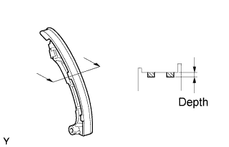
41. INSPECT CHAIN TENSIONER SLIPPER
-
Measure the worn depth of the chain tensioner slipper.
Maximum depth:
1.0 mm (0.0394 in.)
If the depth is more than the maximum, replace the chain tensioner slipper.
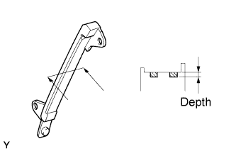
42. INSPECT NO. 1 CHAIN VIBRATION DAMPER
-
Measure the worn depth of the No. 1 chain vibration damper.
Maximum depth:
1.0 mm (0.0394 in.)
If the depth is more than the maximum, replace the No. 1 chain vibration damper.
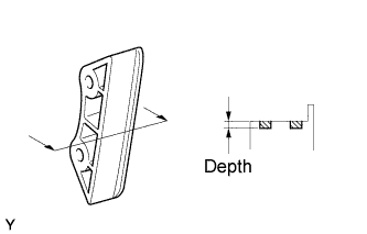
43. INSPECT NO. 2 CHAIN VIBRATION DAMPER
-
Measure the worn depth of the No. 2 chain vibration damper.
Maximum depth:
1.0 mm (0.0394 in.)
If the depth is more than the maximum, replace the No. 2 chain vibration damper.
44. INSPECT EXHAUST MANIFOLD FOR FLATNESS

-
Using a precision straightedge and feeler gauge, measure the warpage of the contact surface of the cylinder head.
Maximum warpage:
0.70 mm (0.0276 in.)
If warpage is more than the maximum, replace the exhaust manifold.
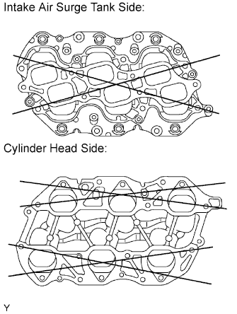
45. INSPECT INTAKE MANIFOLD FOR FLATNESS
-
Using a precision straightedge and feeler gauge, measure the warpage of the contact surface of the cylinder head and intake air surge tank.
Maximum warpage:
for intake air surge tank side: 0.80 mm (0.0315 in.)
for cylinder head side: 0.20 mm (0.00787 in.)
If warpage is more than the maximum, replace the intake manifold.