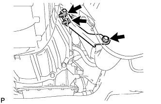
1. INSTALL ENGINE HANGER

-
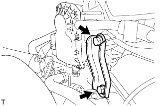
Install 2 engine hangers with 4 bolts as shown in the illustration.
Part No. Item Part No. No. 1 engine hanger 12281-31070 No. 2 engine hanger 12282-31050 Bolt 90119-08A87 Torque:
33 N*m{ 336 kgf*cm , 24 ft.*lbf }
2. REMOVE ENGINE STAND
-
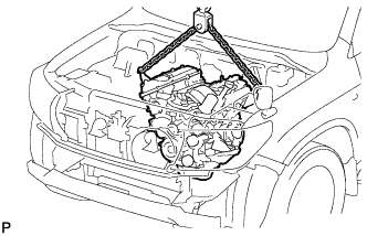
Attach an engine sling device and hang the engine with a chain block.
-
Lift the engine, and remove it from the engine stand.
-
Place the engine onto a work bench.
3. INSTALL ENGINE ASSEMBLY
-
Attach an engine sling device and hang the engine with a chain block.
-
Slowly lower the engine into the engine compartment.
-
Install the front engine mounting insulator LH with the 2 bolts and nut.

Torque:
for bolt:
79 N*m{ 806 kgf*cm , 58 ft.*lbf }
for nut:
72 N*m{ 734 kgf*cm , 53 ft.*lbf }
-
Install the front engine mounting insulator RH with the 2 bolts and nut.
Torque:
for bolt:
79 N*m{ 806 kgf*cm , 58 ft.*lbf }
for nut:
72 N*m{ 734 kgf*cm , 53 ft.*lbf }
-
Remove the 2 engine hangers and 4 bolts.
4. INSTALL DRIVE PLATE AND RING GEAR SUB-ASSEMBLY (for Automatic Transmission)
-
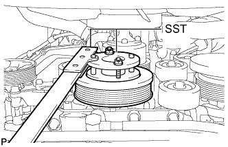
Using SST, hold the crankshaft.
SST
09213-54015 (91651-60855) 09330-00021
-
Temporarily install the front spacer, drive plate and rear spacer with the 8 bolts.
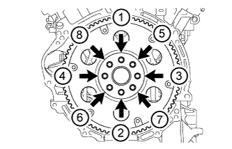
-
Tighten the 8 bolts uniformly in several steps in the order shown in the illustration.
Torque:
83 N*m{ 846 kgf*cm , 61 ft.*lbf }
NOTICE:
Do not start the engine for at least 1 hour after installing.
5. INSTALL FLYWHEEL SUB-ASSEMBLY (for Manual Transmission)
-
Using SST, hold the crankshaft.
SST
09213-54015 (91651-60855) 09330-00021
-
Temporarily install the flywheel with the 8 bolts.
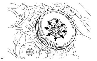
-
Install and tighten the 8 mounting bolts uniformly in several steps.
Torque:
83 N*m{ 846 kgf*cm , 61 ft.*lbf }
6. INSTALL CLUTCH DISC ASSEMBLY (for Manual Transmission)

-
Insert SST into the clutch disc, then insert the clutch disc into the flywheel.
SST
09301-00110
NOTICE:
Take care not to insert the clutch disc in the wrong direction.
7. INSTALL CLUTCH COVER ASSEMBLY (for Manual Transmission)
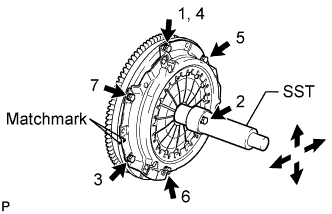
-
Align the matchmark on the clutch cover with the one on the flywheel.
-
In the order shown in the illustration, temporarily install the 6 bolts starting from the bolt located near the knock pin on the top.
-
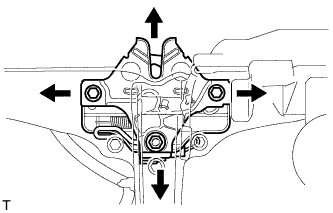
Check that the disc is in the center by lightly moving SST up and down, and left and right.
SST
09301-00110
-
Evenly tighten the bolts by following the order shown in the illustration.
Torque:
19 N*m{ 195 kgf*cm , 14 ft.*lbf }
8. INSPECT AND ADJUST CLUTCH COVER ASSEMBLY (for Manual Transmission)

-
Using a dial indicator with a roller instrument, check the diaphragm spring tip alignment.
Maximum Misalignment:
1.3 mm (0.0512 in.)

-
If the alignment is not as specified, adjust the diaphragm spring tip alignment using SST.
SST
09333-00013
9. CONNECT NO. 1 OIL COOLER HOSE TUBE SUB-ASSEMBLY

-
Connect the cooler hose tube with the 2 bolts.
Torque:
14 N*m{ 143 kgf*cm , 10 ft.*lbf }
10. INSTALL REAR NO. 1 ENGINE MOUNTING INSULATOR

-
Install the rear engine mounting insulator to the transmission with the 4 bolts.
Torque:
59 N*m{ 602 kgf*cm , 44 ft.*lbf }
11. INSTALL MANUAL TRANSMISSION ASSEMBLY (for Manual Transmission)
-
Install the manual transmission to the vehicle.
12. INSTALL AUTOMATIC TRANSMISSION ASSEMBLY (for Automatic Transmission)
-
Install the automatic transmission to the vehicle.
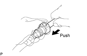
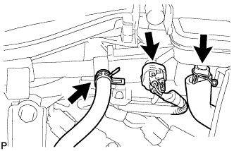
13. CONNECT NO. 1 AND NO. 2 FUEL PIPE
-
Connect the No. 1 and No. 2 fuel pipe.
-
Check that there is no damage or contamination in the connector part of the pipe.
-
Align the axis of the connector with the axis of the pipe. Push the pipe into the connector until the connector makes a "click" sound. If the connection is tight, apply a small amount of fresh engine oil on the tip of the pipe.
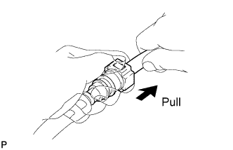
-
After having finished the connection, try to pull apart the pipe and the connector and confirm that they are securely connected.
-
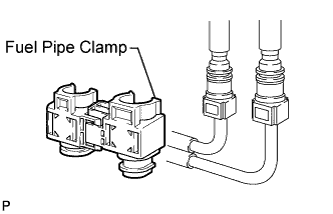
-
Install the fuel pipe clamp to the connector.
14. CONNECT COOLER COMPRESSOR ASSEMBLY
-
Fix the cooler compressor in place with the stud bolt.
Torque:
10 N*m{ 102 kgf*cm , 7 ft.*lbf }

-
Install the cooler compressor with the nut and 3 bolts in several steps in the sequence shown in the illustration.
Torque:
24 N*m{ 250 kgf*cm , 18 ft.*lbf }
-
Connect the cooler compressor connector.
15. INSTALL GENERATOR ASSEMBLY

-
Install the generator with the 2 bolts.
Torque:
43 N*m{ 438 kgf*cm , 32 ft.*lbf }
-
Connect the wire harness clamp bracket with the bolt.
Torque:
8.0 N*m{ 82 kgf*cm , 71 in.*lbf }
-
Install the wire harness clamp to the bracket.
-
Connect the generator wire with the nut.
Torque:
9.8 N*m{ 100 kgf*cm , 87 in.*lbf }
-
Install the terminal cap.
-
Connect the generator connector.
-
Connect the wire harness clamp bracket with the nut.
Torque:
8.0 N*m{ 82 kgf*cm , 71 in.*lbf }
16. INSTALL BATTERY
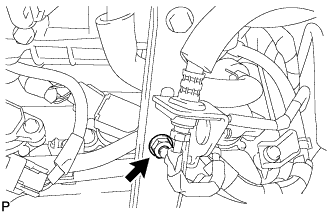
17. CONNECT VANE PUMP ASSEMBLY

-
Connect the vane pump with the 2 bolts.
Torque:
21 N*m{ 214 kgf*cm , 15 ft.*lbf }
-
Connect the power steering oil pressure switch connector.
18. CONNECT WATER HOSE SUB-ASSEMBLY

-
Connect the water hoses.
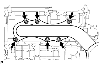
19. INSTALL EXHAUST MANIFOLD SUB-ASSEMBLY LH

-
Set a new gasket to the cylinder head LH with the oval shape facing rearward.
NOTICE:
Be careful of the installation direction.
-
Install the exhaust manifold with 6 new nuts.
Torque:
30 N*m{ 306 kgf*cm , 22 ft.*lbf }
-
Connect the air fuel ratio sensor connector.
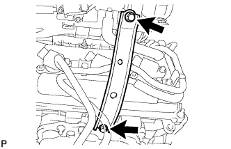
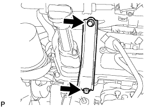
20. INSTALL NO. 2 MANIFOLD STAY
-
Install the No. 2 manifold stay with the 3 bolts.
Torque:
40 N*m{ 408 kgf*cm , 30 ft.*lbf }
21. INSTALL EXHAUST MANIFOLD SUB-ASSEMBLY RH

-
Set a new gasket to the cylinder head RH with the oval shape facing forward.
NOTICE:
Be careful of the installation direction.

-
Install the exhaust manifold with 6 new nuts.
Torque:
30 N*m{ 306 kgf*cm , 22 ft.*lbf }
-
Connect the air fuel ratio sensor connector.
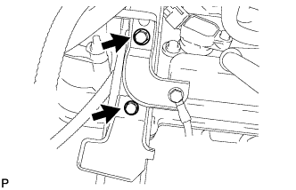
22. INSTALL MANIFOLD STAY
-
Install the No. 1 manifold stay with the 3 bolts.
Torque:
40 N*m{ 408 kgf*cm , 30 ft.*lbf }
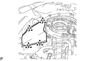
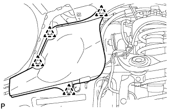
23. INSTALL FRONT FENDER APRON SEAL LH
-
Install the fender apron seal with the 4 clips.
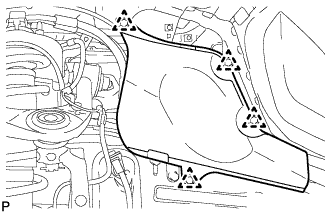
24. INSTALL FRONT FENDER APRON SEAL REAR LH
-
Install the fender apron seal with the 4 clips.
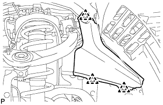
25. INSTALL FRONT FENDER APRON SEAL FRONT RH
-
Install the fender apron seal with the 3 clips.
26. INSTALL FRONT FENDER APRON SEAL REAR RH
-
Install the fender apron seal with the 4 clips.
27. INSTALL FRONT EXHAUST PIPE ASSEMBLY
-
Install a new gasket and the front exhaust pipe to the exhaust manifold RH with 2 new nuts.
Torque:
54 N*m{ 554 kgf*cm , 40 ft.*lbf }
-
Connect the heated oxygen sensor connector.
28. INSTALL FRONT NO. 2 EXHAUST PIPE ASSEMBLY
-
Install a new gasket and the front No. 2 exhaust pipe to the exhaust manifold LH with 2 new nuts.
Torque:
54 N*m{ 554 kgf*cm , 40 ft.*lbf }
-
Connect the heated oxygen sensor connector.
HINT:
Hook the wire harness to the bracket.
29. CONNECT ENGINE WIRE

-
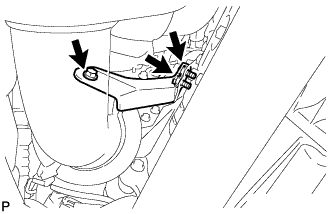
Install the ground cable with the bolt and attach the wire harness clamp.
Torque:
8.4 N*m{ 86 kgf*cm , 74 in.*lbf }

-
Install the battery positive cable with the nut.
Torque:
for nut type A:
13 N*m{ 130 kgf*cm , 9 ft.*lbf }
for nut type B:
7.5 N*m{ 76 kgf*cm , 66 in.*lbf }
HINT:
The torque value differs depending on the shape of the nut that came with the vehicle.
-
Connect the battery positive cable cover.
-
Install the 2 ground cables with the 2 bolts.
Torque:
8.0 N*m{ 82 kgf*cm , 71 in.*lbf }
-
Attach the wire harness clamp to the hose.
-
Attach the wire harness clamp to the body.
-
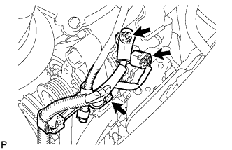
Attach the engine wire to wire connector clamp to the engine room relay block side, and connect the connector.
-
Connect the wire harness with the clamp.
-
Connect the No. 2 engine wire cover to the engine room relay block, and install the No. 2 engine wire with the nut.
Torque:
10 N*m{ 102 kgf*cm , 7 ft.*lbf }
-
Connect the 2 connectors to the engine room relay block.
-
Attach the 2 wire harness clamps and wire harness.
-
Connect the 4 connectors to the junction block.
-
Connect the ECM connector.
-
w/ Winch: Install the winch ground wire with the 2 bolts.
Torque:
Cylinder block side:
19 N*m{ 196 kgf*cm , 14 ft.*lbf }
Body side:
29 N*m{ 300 kgf*cm , 22 ft.*lbf }
30. INSTALL INTAKE AIR SURGE TANK
NOTICE:
Do not apply oil to the bolts and nuts listed below: :
| Oil Application Prohibited Bolt/Nut |
| Bolt for surge tank and intake manifold |
| Nut for surge tank and intake manifold |
-
Install a new gasket to the intake air surge tank.
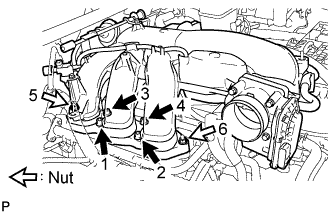
-
Using an 8 mm hexagon wrench, install the intake air surge tank with the 4 bolts and 2 nuts in the order shown in the illustration.
Torque:
28 N*m{ 286 kgf*cm , 21 ft.*lbf }
-
Install the No. 2 surge tank stay with the 2 bolts.
Torque:
21 N*m{ 214 kgf*cm , 15 ft.*lbf }
-
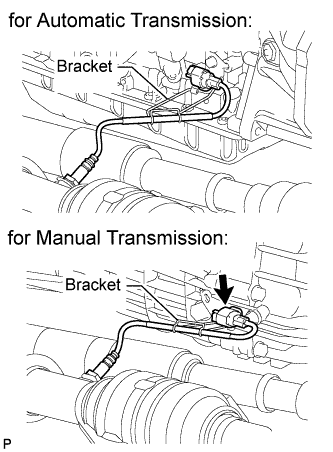
for Manual Transmission:
-
Install the bracket to the No. 2 surge tank stay with the nut.
Torque:
20 N*m{ 204 kgf*cm , 15 ft.*lbf }
-
-
Install the No. 1 surge tank stay with the 2 bolts.
Torque:
21 N*m{ 214 kgf*cm , 15 ft.*lbf }
-
Install the oil baffle plate with the bolt.
Torque:
9.0 N*m{ 92 kgf*cm , 80 in.*lbf }
-
Install the bracket to the No. 1 surge tank stay with the bolt.
Torque:
8.0 N*m{ 82 kgf*cm , 71 in.*lbf }
-
Attach the wire harness clamp.
-
Install the throttle body bracket with the 2 bolts.
Torque:
21 N*m{ 214 kgf*cm , 15 ft.*lbf }
-
Connect the vacuum switching valve (for ACIS) connector.
-
Attach the 2 wire harness clamps.
-
Connect the No. 1 ventilation hose.
-
Connect the purge VSV connector.
-
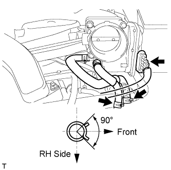
Connect the purge line hose.
HINT:
Connect the hose so that the direction of the hose clamp is as indicated in the illustration.
-
Connect the No. 4 and No. 5 water by-pass hose.
HINT:
Connect the hoses so that the direction of the hose clamps is as shown in the illustration.
-
Connect the throttle body connector.
31. INSTALL AIR CLEANER ASSEMBLY
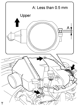
-
Install the air cleaner assembly with the 2 bolts.
Torque:
8.0 N*m{ 82 kgf*cm , 71 in.*lbf }
-
Tighten the hose clamp.
HINT:
Tighten the hose clamp until it reaches the specified protrusion height labeled A shown in the illustration.
Standard protrusion height:
Less than 0.5 mm (0.0197 in.)
-
Connect the MAF meter connector.
-
Attach the 2 wire harness clamps.
-
Connect the vacuum hose.
-
Attach the hose clamp.
-
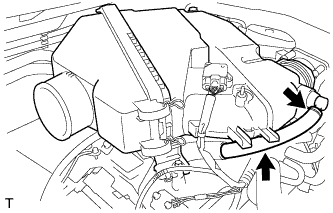
Connect the No. 2 ventilation hose.
32. INSTALL NO. 2 AIR CLEANER HOSE
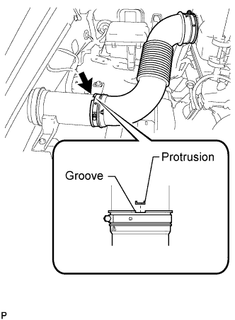
-
Align the protrusion of the pre-cleaner with the groove of the No. 2 air cleaner hose as shown in the illustration.
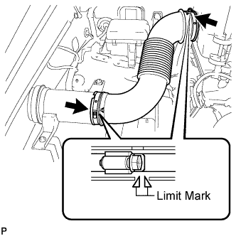
-
Tighten the 2 hose clamps.
Torque:
4.0 N*m{ 41 kgf*cm , 35 in.*lbf }
HINT:
Tighten the clamp until the end of the clamp band is within both limit marks.
33. INSTALL RADIATOR ASSEMBLY
-
Install the radiator assembly.
34. INSTALL COWL TOP VENTILATOR LOUVER SUB-ASSEMBLY
-
Install the cowl top ventilator louver.
35. CONNECT CABLE TO NEGATIVE BATTERY TERMINAL
NOTICE:
When disconnecting the cable, some systems need to be initialized after the cable is reconnected.
36. ADD ENGINE OIL
-
Remove the oil filler cap.
-
Add new oil.
Standard Oil Grade:
Oil Grade Oil Viscosity (SAE) API grade SL "Energy-Conserving", SM "Energy-Conserving", SN "Resource-Conserving" or ILSAC multigrade engine oil 5W-30 10W-30 API grade SL, SM or SN multigrade engine oil 15W-40 20W-50 Standard Oil Capacity:
Item Specified Condition Drain and refill with oil filter change 5.2 liters (5.5 US qts, 4.6 Imp. qts) Drain and refill without oil filter change 4.9 liters (5.2 US qts, 4.3 Imp. qts) Dry fill 6.0 liters (6.3 US qts, 5.3 Imp. qts)
-
Install the oil filler cap.
37. INSPECT FOR FUEL LEAK
-
Connect the intelligent tester to the DLC3.
-
Turn the ignition switch to ON and intelligent tester on.
NOTICE:
Do not start the engine.
-
Enter the following menus: Powertrain / Engine and ECT / Active Test / Activate the Fuel Pump Speed Control.
-
Check that there are no fuel leaks after doing maintenance anywhere on the fuel system.
38. INSPECT FOR OIL LEAK
39. INSPECT FOR EXHAUST GAS LEAK
If gas is leaking, tighten the areas necessary to stop the leak. Replace damaged parts as necessary.
40. CHECK ENGINE OIL LEVEL
-
Warm up the engine so that the coolant temperature is approximately 80°C (176°F). Check the engine oil level dipstick 5 minutes after the engine is stopped. Then add engine oil to the full level of the engine oil level dipstick.
41. INSTALL NO. 2 ENGINE UNDER COVER
42. PERFORM RESET MEMORY (for Automatic Transmission)
-
Perform the Reset Memory procedures.
43. INSPECT IGNITION TIMING
NOTICE:
- Turn all electrical systems off.
- Perform the inspection when the cooling fan motor is turned off.
-
Warm up the engine.
-
When using the intelligent tester:
-
Connect the intelligent tester to the DLC3.
-
Enter the following menus: Powertrain / Engine and ECT / Data List / All Data / IGN Advance.
-
Inspect the ignition timing during idling.
Standard ignition timing:
8 to 12° BTDC @ idling (transmission in neutral position and A/C switch off)
-
Check that the ignition timing advances immediately when the engine speed is increased.
-
-
When not using the intelligent tester:
-
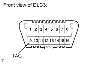
Using SST, connect terminals 13 (TC) and 4 (CG) of the DLC3.
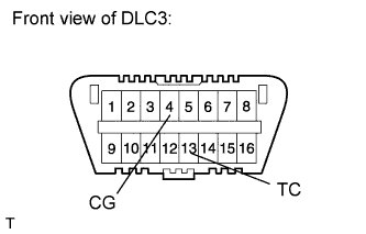
SST
09843-18040
NOTICE:
Be sure not to improperly connect the terminals. This may damage the engine.
-
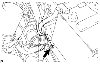
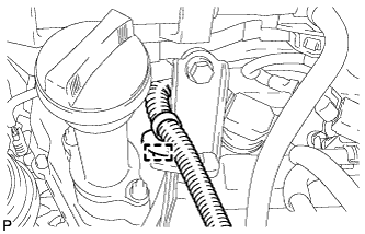
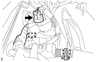
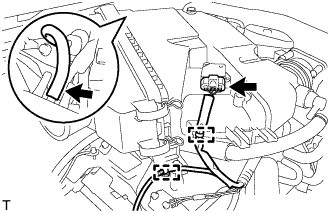
Remove the air cleaner cap.
-
Pull out the wire harness shown in the illustration.
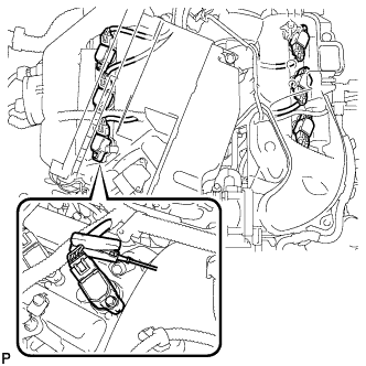
-
Connect the tester probe of a timing light to the wire of the ignition coil connector for the No. 1 cylinder.
NOTICE:
- Use a timing light that detects primary signals.
- After checking, be sure to wrap the wire harness with tape.
-
Inspect the ignition timing during idling.
Standard ignition timing:
8 to 12° BTDC @ idling (transmission in neutral position and A/C switch off)
-
Remove SST from the DLC3.
-
Inspect the ignition timing during idling.
Standard ignition timing:
7 to 24° BTDC @ idling (transmission in neutral position and A/C switch off)
-
Disconnect the timing light from the engine.
-
Install the air cleaner cap.
-
44. INSPECT ENGINE IDLE SPEED
NOTICE:
- Turn all the electrical systems off.
- Perform the inspection when the cooling fan motor is turned off.
-
Warm up the engine.
-
When using the intelligent tester:
-
Connect the intelligent tester to the DLC3.
-
Enter the following menus: Powertrain / Engine and ECT / Data List / All Data / Engine Speed.
-
Inspect the engine idling speed.
Standard idling speed:
650 to 750 rpm (transmission in neutral position and A/C switch off)
-
-
When not using the intelligent tester:
-
Connect SST to terminal 9 (TAC) of the DLC3.
SST
09843-18030
-
Race the engine at 2500 rpm for approximately 90 seconds.
-
Inspect the engine idling speed.
Standard idling speed:
650 to 750 rpm (transmission in neutral position and A/C switch off)
-
45. INSPECT CO/HC
HINT:
This check is to determine whether or not the idle CO/HC concentration complies with regulations.
-
Start the engine.
-
Run the engine at 2500 rpm for approximately 180 seconds.
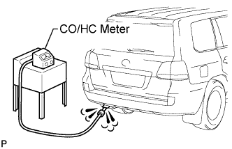
-
Insert the CO/HC meter testing probe at least 40 cm (1.31 ft) into the tailpipe during idling.
-
Immediately check the CO/HC concentration during idling and/or at 2500 rpm.
HINT:
When carrying out the 2 tests (idling and 2500 rpm), the measurement orders are prescribed by the applicable local regulations.
-
If the CO/HC concentration does not comply with regulations, perform troubleshooting in the order given below.
-
Check the A/F sensor operation and heated oxygen sensor operation.
-
See the table below for possible causes, and then inspect and correct the corresponding causes if necessary.
CO HC Symptom Causes Normal High Rough idling - Faulty ignition:
- Incorrect timing
- Plugs are contaminated or shorted, or plug gaps are defective
- Incorrect valve clearance
- Leaky intake and exhaust valves
- Leaky cylinders
Low High Rough idling (Fluctuating HC reading) - Vacuum leaks:
- Ventilation hoses
- Intake manifold
- Throttle body
- Lean mixture causing misfire
High High Rough idle (Black smoke from exhaust) - Restricted air filter
- Faulty SFI system:
- Faulty pressure regulator
- Defective engine coolant temperature sensor
- Faulty mass air flow meter
- Faulty ECM
- Faulty injectors
- Faulty throttle position sensor
- Faulty ignition:
-
46. INSTALL HOOD SUB-ASSEMBLY
-
Install the hood with the 4 bolts.
Torque:
13 N*m{ 133 kgf*cm , 10 ft.*lbf }
47. ADJUST HOOD SUB-ASSEMBLY
-
Adjust the hood position.
-
Loosen the 4 hinge bolts of the hood.
-
Move the hood and adjust the clearance between the hood and front fender.
-
Tighten the 4 hinge bolts of the hood after the adjustment.
Torque:
13 N*m{ 133 kgf*cm , 10 ft.*lbf }
-
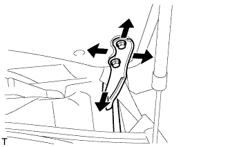
Adjust the cushion rubber so that the height of the hood and fender are aligned.
HINT:
Raise or lower the hood front end by turning the cushion rubber.
-
-
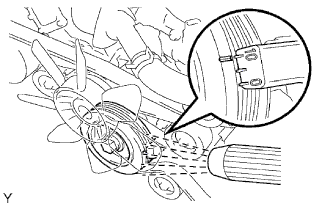
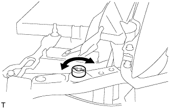
Adjust the hood lock.
-
Using a screwdriver, remove the hood lock nut cap as shown in the illustration.
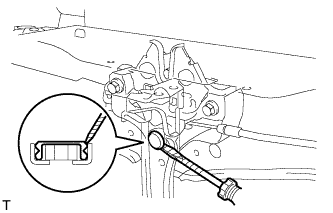
HINT:
Tape the screwdriver tip before use.
-
Loosen the 2 bolts and hood lock nut.
-
Adjust the hood lock position so that the striker can enter it smoothly.
-
Tighten the bolts and nut after the adjustment.
Torque:
5.5 N*m{ 56 kgf*cm , 49 in.*lbf }
-
Install a new cap.
-
48. INSPECT COOLANT LEVEL AT RESERVOIR
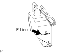
-
Check that the engine coolant level is between the L and F lines when the engine is cold. If the engine coolant is low, check for leaks and add "TOYOTA Super Long Life Coolant" or similar high quality ethylene glycol based non-silicate, non-amine, non-nitrite and non-borate coolant with long-life hybrid organic acid technology to the F line.
NOTICE:
Do not substitute plain water for engine coolant.