1. INSPECT CAMSHAFTS

-
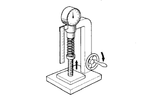
Inspect the camshaft runout.
-
Place the camshaft on V-blocks.
-
Using a dial indicator, measure the runout at the center journal.
Maximum runout:
0.06 mm (0.00236 in.)
If the runout is more than the maximum, replace the camshaft.
-

-
Inspect the cam lobes.
-
Using a micrometer, measure the cam lobe height.
Standard Cam Lobe Height:
Item Specified Condition Intake 44.168 to 44.268 mm (1.739 to 1.742 in.) Exhaust 44.580 to 44.680 mm (1.755 to 1.759 in. Minimum Cam Lobe Height:
Item Specified Condition Intake 44.018 mm (1.73 in.) Exhaust 44.430 mm (1.75 in.) If the cam lobe height is less than the minimum, replace the camshaft.
-
-
Inspect the camshaft journals.
-
Using a micrometer, measure the journal diameter.
Standard Journal Diameter:
Item Specified Condition No. 1 35.971 to 35.985 mm (1.416 to 1.417 in.) Other 22.959 to 22.975 mm (0.904 to 0.905 in.) If the journal diameter is not as specified, check the oil clearance.
-
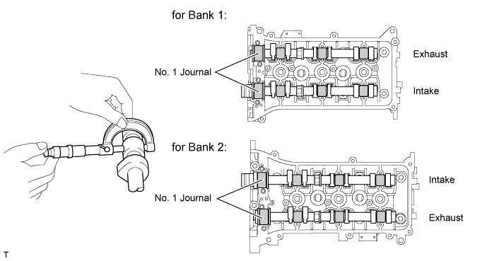
2. INSPECT CAMSHAFT OIL CLEARANCE
-
Clean the camshaft bearing caps, camshaft bearings and camshaft journals.
-
Install the camshaft bearing.
-
Place the camshafts on the cylinder head.
-
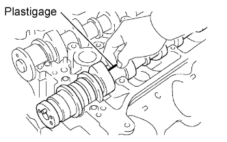
Lay a strip of Plastigage across each of the camshaft journals.
-
Install the camshaft bearing caps.
NOTICE:
Do not turn the camshafts.
-
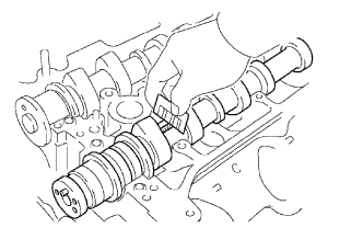
Remove the camshaft bearing caps.
-
Measure the Plastigage at its widest point.
Standard Oil Clearance (for Cylinder Head RH):
Item Specified Condition No. 1 (Intake) 0.008 to 0.038 mm (0.000315 to 0.00150 in.) No. 1 (Exhaust) 0.040 to 0.079 mm (0.00157 to 0.00311 in.) Others 0.025 to 0.062 mm (0.000984 to 0.00244 in.) Standard Oil Clearance (for Cylinder Head LH):
Item Specified Condition No. 1 0.040 to 0.079 mm (0.00157 to 0.00311 in.) Others 0.025 to 0.062 mm (0.000984 to 0.00244 in.) Maximum Oil Clearance (for Cylinder Head RH):
Item Specified Condition No. 1 (Intake) 0.07 mm (0.00276 in.) Others 0.10 mm (0.00394 in.) Maximum Oil Clearance (for Cylinder Head LH):
Item Specified Condition - 0.10 mm (0.00394 in.) If the oil clearance is more than the maximum, replace the camshaft bearings and/or camshaft. If necessary, replace the camshaft bearing caps and cylinder head together.
Reference:
Item Specified Condition Cylinder head journal bore diameter 40.009 to 40.017 mm (1.5752 to 1.5755 in.) Camshaft bearing center wall thickness (Mark "2") 2.004 to 2.008 mm (0.0789 to 0.0791 in.) Camshaft journal diameter 35.971 to 35.985 mm (1.4162 to 1.4167 in.)
-
Remove the Plastigage completely.
-
Remove the camshafts.
-
Remove the camshaft bearing.
3. INSPECT CAMSHAFT THRUST CLEARANCE

-
Install the camshafts.
-
Using a dial indicator, measure the thrust clearance while moving the camshaft back and forth.
Standard thrust clearance:
0.04 to 0.09 mm (0.00157 to 0.00354 in.)
Maximum thrust clearance:
0.11 mm (0.00433 in.)
If the thrust clearance is more than the maximum, replace the camshafts. If necessary, replace the camshaft bearing caps and cylinder head as a set.
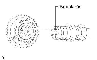
4. INSPECT CAMSHAFT TIMING GEAR ASSEMBLY
-
Fix the intake camshaft with a vise.
NOTICE:
Be careful not to damage the camshaft.
-
Align the knock pin hole in the camshaft timing gear with the knock pin of the camshaft, and install the camshaft timing gear with the bolt.
Torque:
100 N*m{ 1020 kgf*cm , 74 ft.*lbf }
-
Confirm the camshaft timing gear is locked.
-
Release the lock pin.
-
Cover the 4 oil paths of the cam journal with vinyl tape as shown in the illustration.
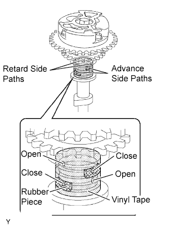
HINT:
One of the 2 grooves on the cam journal is for retard side paths (upper) and the other is for advance side paths (lower). Each groove has 2 oil paths. Plug one of the oil paths for each groove with rubber pieces as shown in the illustration before wrapping the cam journal with tape.
-
Prink a hole in the tape at the 2 oil holes not plugged with rubber pieces.
-
Apply about 200 kPa (2.0 kgf/cm2, 28 psi) of air pressure to the two broken paths (the advance side path and the retard side path).

NOTICE:
Cover the paths with a cloth to avoid oil splashing.
-
Confirm that the camshaft timing gear rotates in the advance direction when reducing the air pressure applied to the retard path.
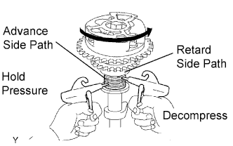
HINT:
When the lock pin is released, the camshaft timing gear rotates in the advance direction.
-
When the camshaft timing gear comes to the most advanced position, release the air pressure from the retard side path, and then release the air pressure from the advance side path.
NOTICE:
The camshaft timing gear occasionally shifts to the retard side abruptly if air compression of the advanced side path is released first. This often results in the breakage of the lock pin.
-
-
Check for smooth rotation.
-
Except the position where the lock pin meets at the most retarded angle, turn the camshaft timing gear back and forth and check the movable range and that there is no disturbance.
Standard:
Movable smoothly in the range of about 31°
NOTICE:
Be sure to perform this check by hand, instead of with air pressure.
-
-
Check the lock in the most retarded position.
-
Confirm that the camshaft timing gear is locked at the most retarded position.
-
-
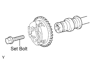
Remove the set bolt and camshaft timing gear.
NOTICE:
Be sure not to remove the other 3 bolts.
5. INSPECT CAMSHAFT TIMING GEAR ASSEMBLY
-
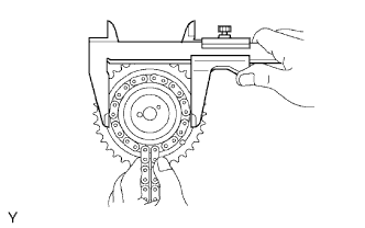
Wrap the No. 1 chain around the gear place for the No. 1 chain.
-
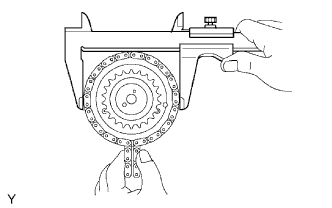
Using a vernier caliper, measure the timing gear with the No. 1 chain.
Minimum gear diameter (with chain):
115.5 mm (4.55 in.)
HINT:
The vernier caliper must contact the chain rollers for the measurement.
If the diameter is less than the minimum, replace the No. 1 chain and camshaft timing gear assembly.
-
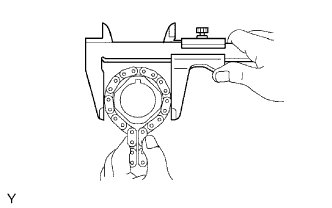
Wrap the No. 2 chain around the gear place for the No. 2 chain.
-
Using a vernier caliper, measure the timing gear with the No. 2 chain.
Minimum gear diameter (with chain):
73.1 mm (2.88 in.)
HINT:
The vernier caliper must contact the chain rollers for the measurement.
If the diameter is less than the minimum, replace the No. 2 chain and camshaft timing gear assembly.
6. INSPECT CAMSHAFT TIMING SPROCKET
-
Wrap the No. 1 chain around the sprocket.
-
Using a vernier caliper, measure the crankshaft timing sprocket diameter with the No. 1 chain.
Minimum gear diameter (with chain):
61.0 mm (2.40 in.)
HINT:
The vernier caliper must contact the chain rollers for the measurement.
If the diameter is less than the minimum, replace the No. 1 chain and crankshaft timing sprocket.
7. INSPECT INNER COMPRESSION SPRING

-
Using a steel square, measure the deviation of the inner compression spring.
Maximum deviation:
2.0 mm (0.0787 in.)
If the deviation is more than the maximum, replace the inner compression spring.
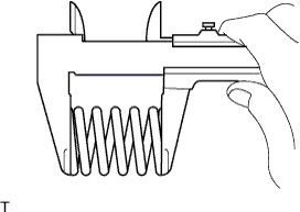
-
Using a vernier caliper, measure the free length of the inner compression spring.
Standard free length:
47.80 mm (1.88 in.)
If the free length is not as specified, replace the inner compression spring.
-
Using a spring tester, measure the tension of the inner compression spring at the standard installed length.
Standard installed tension:
186 to 206 N (19 to 21 kgf, 42 to 46 lbf) at 33.3 mm (1.31 in.)
If the installed tension is not as specified, replace the inner compression spring.
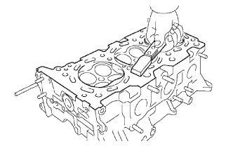
8. CLEAN VALVE

-
Using a gasket scraper, chip off any carbon from the valve head.
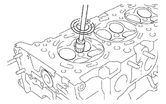
-
Using a wire brush, thoroughly clean the valve.
9. INSPECT VALVE
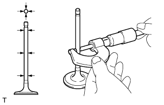
-
Using a micrometer, measure the diameter of the valve stem.
Standard Valve Stem Diameter:
Item Specified Condition Intake 5.470 to 5.485 mm (0.2154 to 0.2159 in.) Exhaust 5.465 to 5.480 mm (0.2152 to 0.2156 in.)

-
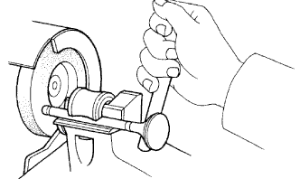
Inspect the valve face angle.
-
Grind the valve enough to remove pits and carbon.
-
Check that the valve is ground to the correct valve face angle.
Standard valve face angle:
44.5°
-

-
Using a vernier caliper, measure the valve head margin thickness.
-
Using a vernier caliper, check the valve head margin thickness.
Standard margin thickness:
1.0 mm (0.0394 in.)
Minimum margin thickness:
0.5 mm (0.0197 in.)
If the margin thickness is less than the minimum, replace the valve.
-

-
Using a vernier caliper, measure the overall length of the valve.
-
Using a vernier caliper, check the overall length.
Standard Overall Length:
Item Specified Condition Intake 106.95 mm (4.21 in.) Exhaust 105.80 mm (4.15 in.) Minimum Overall Length:
Item Specified Condition Intake 106.40 mm (4.19 in.) Exhaust 105.30 mm (4.15 in.) If the overall length is less than the minimum, replace the valve.
-
-
Inspect the valve stem tip.
-
Check the surface of the valve stem tip for wear.
NOTICE:
Do not grind the valve so it becomes shorter than the minimum overall length.
If the valve stem tip is worn, resurface the tip with a grinder or replace the valve.
-
10. INSPECT VALVE GUIDE BUSH OIL CLEARANCE

-
Using a caliper gauge, measure the inside diameter of the guide bush.
Standard bush inside diameter:
5.51 to 5.53 mm (0.217 to 0.218 in.)
-
Subtract the valve stem diameter measurement from the guide bush inside diameter measurement.
Standard Oil Clearance:
Item Specified Condition Intake 0.025 to 0.060 mm (0.000984 to 0.00236 in.) Exhaust 0.030 to 0.065 mm (0.00118 to 0.00256 in.) Maximum Oil Clearance:
Item Specified Condition Intake 0.08 mm (0.00315 in.) Exhaust 0.10 mm (0.00394 in.) If the oil clearance is more than the maximum, replace the valve and valve guide bush.
11. INSPECT VALVE LIFTER
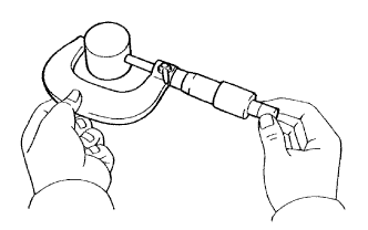
-
Using a micrometer, measure the valve lifter diameter.
Standard valve lifter diameter:
30.966 to 30.976 mm (1.219 to 1.220 in.)
If the result is not as specified, replace the valve lifter.
12. INSPECT VALVE LIFTER OIL CLEARANCE
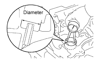
-
Using a caliper gauge, measure the lifter bore diameter of the cylinder head.
Standard lifter bore diameter:
31.009 to 31.025 mm (1.220 to 1.221 in.)
-
Subtract the valve lifter diameter measurement (see "Inspect Valve Lifter" procedure) from the lifter bore diameter measurement.
Standard oil clearance:
0.033 to 0.059 mm (0.00130 to 0.00232 in.)
Maximum oil clearance:
0.08 mm (0.00315 in.)
If the oil clearance is more than the maximum, replace the valve lifter. If necessary, replace the cylinder head.
13. CLEAN CYLINDER HEAD SUB-ASSEMBLY
-
Using a gasket scraper, remove all the gasket material from the cylinder block contact surface.
NOTICE:
Be careful not to scratch the cylinder block contact surface.
-
Using a wire brush, remove all the carbon from the combustion chambers.
NOTICE:
Be careful not to scratch the combustion chambers.

-
Using a valve guide bushing brush and solvent, clean all the valve guide bushes.
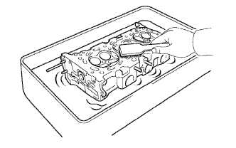
-
Using a soft brush and solvent, thoroughly clean the cylinder head.
14. INSPECT CYLINDER HEAD SUB-ASSEMBLY
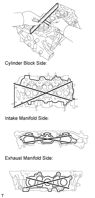
-
Using a precision straightedge and feeler gauge, measure the warpage of the contact surfaces of the cylinder block and manifolds.
Standard Warpage:
Item Specified Condition Cylinder block side 0.05 mm (0.00197 in.) Intake manifold side 0.08 mm (0.00315 in.) Exhaust manifold side 0.08 mm (0.00315 in.) Maximum Warpage:
Item Specified Condition Cylinder block side 0.10 mm (0.00394 in.) Intake manifold side 0.10 mm (0.00394 in.) Exhaust manifold side 0.10 mm (0.00394 in.) If the warpage is more than the maximum, replace the cylinder head sub-assembly.

-
Using a dye penetrant, check the intake ports, exhaust ports and cylinder surface for cracks. If there are cracks, replace the cylinder head sub-assembly.
15. CLEAN VALVE SEAT
-
Using a 45° carbide cutter, resurface the valve seats.
-
Clean the valve seats.
16. INSPECT VALVE SEAT
-
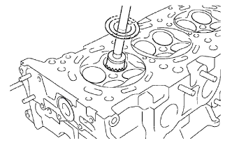
Apply a light coat of Prussian blue to the valve face.
-
Lightly press the valve face against the valve seat.
NOTICE:
Do not rotate the valve.
-
Check the valve face and valve seat by using the following procedure.
-
If Prussian blue appears around the entire valve face, the valve face is concentric. If not, replace the valve.
-
If Prussian blue appears around the entire valve seat, the guide and valve face are concentric. If not, resurface the valve seat.
-
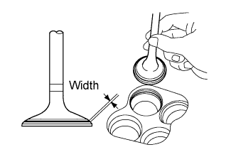
Check that the seat contacts the middle of the valve face with the width below.
Standard width:
1.0 to 1.4 mm (0.0394 to 0.0551 in.)
-