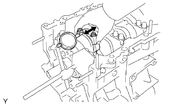
1. INSPECT CONNECTING ROD THRUST CLEARANCE
-
Using a dial indicator, measure the thrust clearance while moving the connecting rod back and forth.
Standard thrust clearance:
0.15 to 0.30 mm (0.00591 to 0.0118 in.)
Maximum thrust clearance:
0.35 mm (0.0138 in.)
If the thrust clearance is more than the maximum, replace one or more connecting rods as necessary. If necessary, replace the crankshaft.
2. REMOVE PISTON SUB-ASSEMBLY WITH CONNECTING ROD

-
Using a ridge reamer, remove all the carbon from the top of the cylinder.
-
Uniformly loosen the connecting rod bolts, and remove the connecting rod cap with bearing.
-
Push out the piston with connecting rod and upper bearing through the top of the cylinder block.
HINT:
- Keep the bearings, connecting rod and cap together.
- Arrange the piston and connecting rod assemblies in the correct order.
3. REMOVE CONNECTING ROD BEARING
4. REMOVE PISTON RING SET

-
Using a piston ring expander, remove the 2 compression rings.
-
Remove the 2 side rails and oil ring (expander) by hand.
5. REMOVE PISTON PIN HOLE SNAP RING

-
Using a screwdriver, pry out the 2 snap rings.
6. REMOVE PISTON WITH PIN SUB-ASSEMBLY
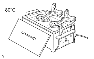
-
Gradually heat the piston to approximately 80°C (176°F).

-
Using a plastic-faced hammer and brass bar, lightly tap out the piston pin and remove the connecting rod.
HINT:
- The piston and pin are a matched set.
- Arrange the pistons, pins, rings, connecting rods and bearings in the correct order.
7. INSPECT CRANKSHAFT THRUST CLEARANCE
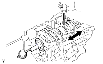
-
Using a dial indicator, measure the thrust clearance while prying the crankshaft back and forth with a screwdriver.
Standard thrust clearance:
0.04 to 0.24 mm (0.00157 to 0.00945 in.)
Maximum thrust clearance:
0.30 mm (0.0118 in.)
If the thrust clearance is more than the maximum, replace the thrust washers as a set.
Standard thrust washer thickness:
1.93 to 1.98 mm (0.0760 to 0.0780 in.)
If necessary, replace the crankshaft.
8. REMOVE CRANKSHAFT

-
Using several steps, loosen and remove the 8 bearing cap bolts and seal washers uniformly in the sequence shown in the illustration.

-
Using several steps, loosen and remove the 16 bearing cap bolts uniformly in the sequence shown in the illustration.

-
Using a screwdriver, pry out the bearing caps. Remove the 4 bearing caps and lower bearings.
NOTICE:
- Push up on the cap little by little, alternating from the right and left side until the cap can be removed.
- Be careful not to damage the joint surfaces of the cylinder block and bearing cap.
9. REMOVE CRANKSHAFT BEARING
10. REMOVE NO. 1 OIL NOZZLE SUB-ASSEMBLY

-
Using a 5 mm hexagon socket wrench, remove the 3 bolts and 3 oil nozzles.