CHECK ANY OTHER DTCS OUTPUT (IN ADDITION TO DTC P0016, P0017, P0018 OR P0019)
PERFORM ACTIVE TEST USING INTELLIGENT TESTER (OPERATE OCV)
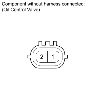
INSPECT CAMSHAFT OIL CONTROL VALVE (FOR INTAKE SIDE OR EXHAUST SIDE)
REPLACE CAMSHAFT TIMING GEAR OR CAMSHAFT TIMING EXHAUST GEAR
CONFIRM WHETHER DTC OUTPUT RECURS
DTC P0016 Crankshaft Position - Camshaft Position Correlation (Bank 1 Sensor A)
DTC P0017 Crankshaft Position - Camshaft Position Correlation (Bank 1 Sensor B)
DTC P0018 Crankshaft Position - Camshaft Position Correlation (Bank 2 Sensor A)
DTC P0019 Crankshaft Position - Camshaft Position Correlation (Bank 2 Sensor B)
Description
In the VVT (Variable Valve Timing) system, the appropriate intake and exhaust valve open and close timing is controlled by the ECM. The ECM performs intake and exhaust valve control by performing the following: 1) controlling the camshaft and camshaft timing oil control valve, and operating the camshaft timing gear; and 2) changing the relative positions of the camshaft and crankshaft.
| DTC Code | DTC Detection Condition | Trouble Area |
| P0016 | Deviation in the crankshaft position sensor signal and VVT sensor (for Intake side of Bank 1) signal (2 trip detection logic). |
|
| P0017 | Deviation in the crankshaft position sensor signal and VVT sensor (for Exhaust side of Bank 1) signal (2 trip detection logic). |
|
| P0018 | Deviation in the crankshaft position sensor signal and VVT sensor (for Intake side of Bank 2) signal (2 trip detection logic). |
|
| P0019 | Deviation in the crankshaft position sensor signal and VVT sensor (for Exhaust side of Bank 2) signal (2 trip detection logic). |
|
Monitor description
To monitor the correlation of the intake camshaft position and crankshaft position, the ECM checks the VVT learning value while the engine is idling. The VVT learning value is calibrated based on the camshaft position and crankshaft position. The intake valve timing is set to the most retarded angle while the engine is idling. If the VVT learning value is out of the specified range in consecutive driving cycles, the ECM illuminates the MIL and stores DTC P0016 (Bank 1) or P0018 (Bank 2). To monitor the correlation of the exhaust camshaft position and crankshaft position, the ECM checks the VVT learning value while the engine is idling. The VVT learning value is calibrated based on the camshaft position and crankshaft position. The exhaust valve timing is set to the most advanced angle while the engine is idling. If the VVT learning value is out of the specified range in consecutive driving cycles, the ECM illuminates the MIL and stores DTC P0017 (Bank 1) or P0019 (Bank 2).
Wiring diagram
Refer to DTC P0335. Refer to DTC P0340. Refer to DTC P0365.
Inspection procedure
HINT:
- Read freeze frame data using the intelligent tester. Freeze frame data records the engine condition when malfunctions are detected. When troubleshooting, freeze frame data can help determine if the vehicle was moving or stationary, if the engine was warmed up or not, if the air-fuel ratio was lean or rich, and other data from the time the malfunction occurred.
- Bank 1 refers to the bank that includes the No. 1 cylinder*. *: The No. 1 cylinder is the cylinder which is farthest from the transmission.
- Bank 2 refers to the bank that does not include the No. 1 cylinder.
| 1.CHECK ANY OTHER DTCS OUTPUT (IN ADDITION TO DTC P0016, P0017, P0018 OR P0019) |
-
Connect the intelligent tester to the DLC3.
-
Turn the engine switch on (IG) and turn the tester on.
-
Enter the following menus: Powertrain / Engine and ECT / DTC.
-
Read DTCs.
Result Result Proceed to P0016, P0017, P0018 or P0019 is output A P0016, P0017, P0018 or P0019 and other DTCs are output B
|
|
||||
| A | |
| 2.PERFORM ACTIVE TEST USING INTELLIGENT TESTER (OPERATE OCV) |
HINT:
If the VVT system can be operated through the Active Test, it can be assumed that the VVT system is operating normally.
-
Connect the intelligent tester to the DLC3.
-
Start the engine.
-
Turn the A/C on.
-
Turn the tester on
-
Warm up the engine.
-
Enter the following menus: Powertrain / Engine and ECT / Active Test / Control the VVT Linear (Bank 1) or Control the VVT Linear (Bank 2) or Control the VVT Exhaust Linear (Bank 1) or Control the Exhaust VVT Linear (Bank 2) / All Data / VVT Change Angle #1, VVT Change Angle #2, VVT Ex Chg Angle #1, VVT Ex Chg Angle #2.
-
Perform the Active Test. Check that the displacement angle varies.
OK:
Displacement angle varies.
|
|
||||
| OK | |
| 3.ADJUST VALVE TIMING |
-
Adjust the valve timing .
|
|
||||
| 4.INSPECT CAMSHAFT OIL CONTROL VALVE (FOR INTAKE SIDE OR EXHAUST SIDE) |

-
Remove the OCV.
-
Measure the resistance according to the value(s) in the table below.
Standard Resistance:
Tester Connection Condition Specified Condition 1 - 2 20°C (68°F) 6.9 to 7.9 ?
-
Check the valve operation.
OK:
Measurement Condition Specified Condition No battery voltage applied to terminals 1 and 2 > Battery voltage applied to terminals 1 and 2 Valve moves quickly
|
|
||||
| OK | |
| 5.REPLACE CAMSHAFT TIMING GEAR OR CAMSHAFT TIMING EXHAUST GEAR |
-
Replace the camshaft timing gear .
-
Replace the camshaft timing exhaust gear .
| NEXT | |
| 6.CONFIRM WHETHER DTC OUTPUT RECURS |
-
Connect the intelligent tester to the DLC3.
-
Turn the engine switch on (IG) and turn the tester on.
-
Clear the DTC .
-
Start the engine and warm it up.
-
Switch the ECM from normal mode to check mode using the tester .
-
Drive the vehicle in an urban area for approximately 10 minutes.
-
Read DTCs using the tester.
OK:
No DTC is output.
|
|
||||
| OK | |
|