Fuel Tank -- Installation |
| 1. INSTALL FUEL TANK TO FILLER PIPE HOSE |
Install the fuel tank to filler pipe hose to the fuel tank.
 |
| 2. INSTALL FUEL TANK BREATHER HOSE |
Install the fuel tank breather hose to the fuel tank.
| 3. INSTALL FUEL TANK VENT TUBE SUB-ASSEMBLY |
Apply a light coat of gasoline or grease to a new gasket, and install it to the fuel tank.
Install the fuel tank vent tube to the fuel tank.
- NOTICE:
- Be careful not to bend the arm of the fuel sender gauge.
Set the fuel pump gauge retainer on the fuel tank. While holding the fuel tank vent tube, tighten the retainer one complete turn by hand.
Set SST on the fuel pump gauge retainer.
- SST
- 09808-14030
- HINT:
- Hold the fuel tank vent tube sub-assembly upright by hand to ensure that the gasket is not moved out of position.
- Engage the claws of SST securely with the fuel pump gauge retainer holes to secure SST.
- Install SST while pressing the claws of SST against the fuel pump gauge retainer (toward the center of SST).
 |
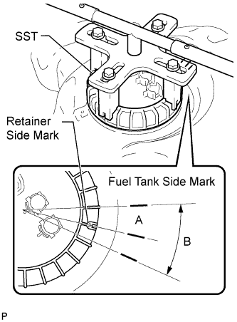
Using SST, tighten the fuel pump gauge retainer until the mark on the fuel pump gauge retainer aligns with mark A on the fuel tank, as shown in the illustration.
- SST
- 09808-14030
- HINT:
- If the alignment is difficult, make sure the mark on the fuel pump gauge retainer is within range B on the fuel tank.
- Fit the tips of SST onto the ribs of the fuel pump gauge retainer.
 |
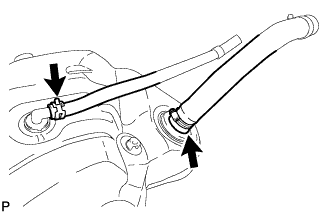
Install the fuel tank return tube and fuel tank main tube to the fuel tank.
Install the 2 fuel tank tubes with the 2 tube joint clips.
- NOTICE:
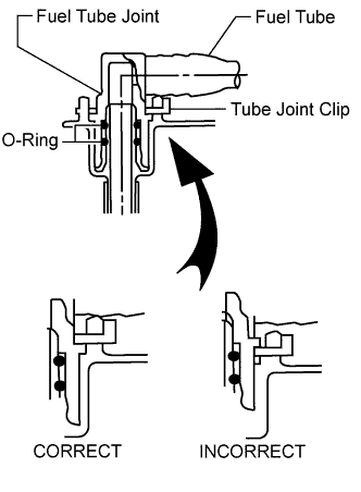
- Check that there are no scratches or foreign objects on the connecting parts.
- Check that the fuel tube joints are inserted securely.
- Check that the tube joint clips are on the collars of the fuel tube joints.
- After installing the tube joint clips, check that the fuel tube joints cannot be pulled off.
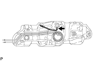
| 4. INSTALL NO. 1 FUEL EVAPORATION TUBE SUB-ASSEMBLY |
Install the No. 1 fuel evaporation tube.
 |
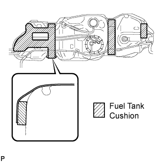
| 5. INSTALL FUEL TANK CUSHION |
Install 4 new fuel tank cushions.
 |
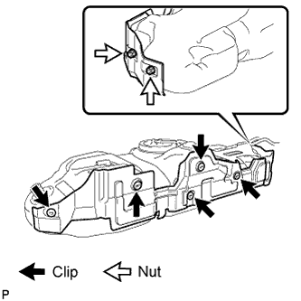
| 6. INSTALL NO. 1 FUEL TANK PROTECTOR SUB-ASSEMBLY |
Install the No. 1 fuel tank protector with the 5 clips and 2 nuts.
- Torque:
- 6.0 N*m{61 kgf*cm, 53 in.*lbf}
 |
| 7. INSTALL FUEL TANK ASSEMBLY |
Set the fuel tank on a transmission jack and raise the fuel tank.
- NOTICE:
- Do not allow the fuel tank to contact the vehicle, especially the differential.
Fold back approximately half of each cushion so that the wire harness can be installed in the step below.
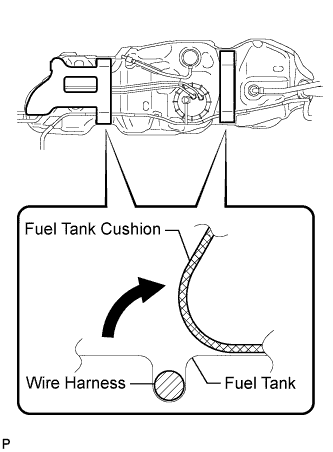 |
Attach the wire harness to the 4 clamps and connect the fuel pump and sender gauge connector.
- NOTICE:
- Be careful not to cut the wirings.
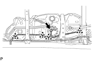 |
Install the 3 fuel tank bands with the 3 pins and 3 clips.
Connect the 3 fuel tank bands with the 3 bolts.
- Torque:
- 61 N*m{622 kgf*cm, 45 in.*lbf}
 |
| 8. INSTALL FUEL TANK FILLER PIPE |
Install the filler pipe with the bolt and nut.
- Torque:
- 19 N*m{194 kgf*cm, 14 ft.*lbf}
| 9. CONNECT FUEL TANK TO FILLER PIPE HOSE |
Connect the fuel tank to filler pipe hose to the fuel tank filler pipe.
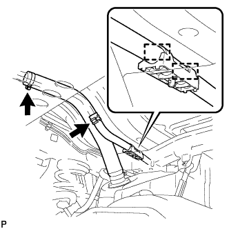 |
| 10. CONNECT FUEL TANK BREATHER HOSE |
Attach the breather hose to the 2 clamps.
Connect the fuel tank breather hose to the fuel tank filler pipe.
| 11. CONNECT FUEL TANK MAIN TUBE SUB-ASSEMBLY AND FUEL TANK RETURN TUBE |
Connect the fuel tank main tube and fuel tank return tube.
 |
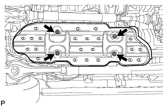
| 12. INSTALL FUEL TANK PROTECTOR |
Install the fuel tank protector with the 4 nuts.
- Torque:
- 20 N*m{204 kgf*cm, 15 ft.*lbf}
 |
| 13. INSTALL FUEL TANK CAP ASSEMBLY |
| 14. BLEED AIR FROM FUEL SYSTEM |
 |
Using the hand pump, bleed air from the fuel system until pumping becomes difficult.
| 15. CONNECT CABLE TO NEGATIVE BATTERY TERMINAL |
- NOTICE:
- When disconnecting the cable, some systems need to be initialized after the cable is reconnected (Toyota Fortuner RM000004W63000X.html).
| 16. CHECK FOR FUEL LEAK |
Check that there are no fuel leaks anywhere on the fuel system after performing maintenance.
- HINT:
- When checking for fuel leaks, make sure that there is pressure in the fuel line.