Vehicle Stability Control System Vsc Off Indicator Light Remains On
DESCRIPTION
WIRING DIAGRAM
INSPECTION PROCEDURE
CHECK FOR DTC
CHECK TERMINAL VOLTAGE (EXI3 TERMINAL)
CHECK HARNESS AND CONNECTOR (EXI3 TERMINAL CIRCUIT)
INSPECT REAR DIFFERENTIAL LOCK SYSTEM
READ VALUE USING INTELLIGENT TESTER (TRC/VSC OFF MODE)
PERFORM ACTIVE TEST USING INTELLIGENT TESTER (VSC WARNING LIGHT)
INSPECT VSC OFF SWITCH
CHECK HARNESS AND CONNECTOR (SKID CONTROL ECU - VSC OFF SWITCH)
CHECK HARNESS AND CONNECTOR (SKID CONTROL ECU - COMBINATION METER)
VEHICLE STABILITY CONTROL SYSTEM - VSC OFF Indicator Light Remains ON |
DESCRIPTION
If the skid control ECU (brake actuator assembly) stores a DTC, the VSC OFF indicator light blinks in the combination meter.Pressing the VSC OFF switch turns off traction control and pressing and holding this switch turns off traction control and VSC. If VSC turns off, the VSC OFF indicator light will come on.for 4WD:When the transfer position is LL, VSC is prohibited and the VSC OFF indicator and slip indicator lights turn on.w/ Rear Differential Lock:When the rear differential is locked, VSC is prohibited, and the VSC OFF indicator and slip indicator lights turn on.
WIRING DIAGRAM
INSPECTION PROCEDURE
- NOTICE:
- As there may be malfunctions in the transfer system related to when the transfer operates in LL, check the transfer system first (Toyota Fortuner RM00000112G003X.html).
- After replacing the brake actuator assembly, perform calibration (Toyota Fortuner RM000000XHR06WX.html).
- Before disconnecting the connector, make sure that there are no problems with the connection.
- After disconnecting the connector, make sure that the connector case and terminals are not deformed or corroded.
Check if DTCs for the VSC are output (Toyota Fortuner RM000000XHV0C7X.html).
ResultResult
| Proceed to
|
DTC is not output
| A
|
DTC is output
| B
|
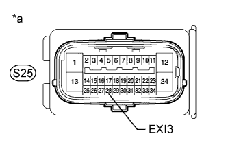
| 2.CHECK TERMINAL VOLTAGE (EXI3 TERMINAL) |
Turn the ignition switch off.
Disconnect the skid control ECU (brake actuator assembly) connector.
Measure the voltage according to the value(s) in the table below.
- Standard Voltage:
Tester Connection
| Switch Condition
| Specified Condition
|
S25-28 (EXI3) - Body ground
| Ignition switch ON
| 11 to 14 V
|
Text in Illustration*a
| Front view of wire harness connector
(to Skid Control ECU [Brake Actuator Assembly])
|
ResultResult
| Proceed to
|
NG
| w/ Rear Differential Lock
| A
|
w/o Rear Differential Lock
| B
|
OK
| C
|
| | REPAIR OR REPLACE HARNESS OR CONNECTOR |
|
|
| |
|
| 3.CHECK HARNESS AND CONNECTOR (EXI3 TERMINAL CIRCUIT) |
Turn the ignition switch off.
Disconnect the rear differential lock position switch (No. 4 transfer indicator switch) connector.
Disconnect the rear differential lock ECU (4 wheel drive control ECU) connector.
Disconnect the skid control ECU (brake actuator assembly) connector.
Disconnect the C28 combination meter connector.
Measure the resistance according to the value(s) in the table below.
- Standard Resistance:
Tester Connection
| Condition
| Specified Condition
|
S25-28 (EXI3) - T29-2
| Always
| Below 1 Ω
|
S25-28 (EXI3) - C28-9
| Always
| Below 1 Ω
|
S25-28 (EXI3) - F18-1 (RLP)
| Always
| Below 1 Ω
|
S25-28 (EXI3) - Body ground
| Always
| 10 kΩ or higher
|
| | REPAIR OR REPLACE HARNESS OR CONNECTOR |
|
|
| 4.INSPECT REAR DIFFERENTIAL LOCK SYSTEM |
| 5.READ VALUE USING INTELLIGENT TESTER (TRC/VSC OFF MODE) |
Turn the ignition switch off.
Connect the intelligent tester to the DLC3.
Turn the ignition switch to ON.
Turn the intelligent tester on.
Enter the following menus: Chassis / ABS/VSC/TRC / Data List.
ABS/VSC/TRCTester Display
| Measurement Item / Range
| Normal Condition
| Diagnostic Note
|
TRC/VSC Off Mode
| VSC OFF switch / Normal, Unknown, TRC OFF or VSC OFF
| Normal: Normal mode
TRC OFF: TRC off mode
VSC OFF: VSC off mode
| -
|
Check that the mode display changes according to VSC OFF switch operation.
- OK:
- The intelligent tester display changes according to VSC OFF switch operation.
| 6.PERFORM ACTIVE TEST USING INTELLIGENT TESTER (VSC WARNING LIGHT) |
Turn the ignition switch off.
Connect the intelligent tester to the DLC3.
Turn the ignition switch to ON.
Turn the intelligent tester on.
Enter the following menus: Chassis / ABS/VSC/TRC / Active Test.
ABS/VSC/TRCTester Display
| Test Part
| Control Range
| Diagnostic Note
|
VSC Warning Light
| VSC OFF indicator light
| Indicator light ON / OFF
| Observe the combination meter.
|
When performing the VSC Warning Light Active Test, check VSC Warning Light in the Data List.
ABS/VSC/TRCTester Display
| Measurement Item / Range
| Normal Condition
| Diagnostic Note
|
VSC Warning Light
| VSC OFF indicator light / ON or OFF
| ON: VSC OFF indicator light on
OFF: VSC OFF indicator light off
| -
|
ResultResult
| Proceed to
|
Data List Display
| Data List Display When Performing Active Test ON/OFF Operation
|
ON
| Does not change between ON and OFF
| A
|
Changes between ON and OFF
| B
|
OFF
| Does not change between ON and OFF
| A
|
Changes between ON and OFF
| B
|
Turn the ignition switch off.
Remove the VSC OFF switch (Toyota Fortuner RM000001WZ200QX.html).
Inspect the VSC OFF switch (Toyota Fortuner RM000001WZ000SX.html).
| 8.CHECK HARNESS AND CONNECTOR (SKID CONTROL ECU - VSC OFF SWITCH) |
Turn the ignition switch off.
Disconnect the VSC OFF switch connector.
Disconnect the skid control ECU (brake actuator assembly) connector.
Measure the resistance according to the value(s) in the table below.
- Standard Resistance:
Tester Connection
| Condition
| Specified Condition
|
S25-30 (CSW) - V5-3
| Always
| Below 1 Ω
|
S25-30 (CSW) - Body ground
| Always
| 10 kΩ or higher
|
V5-4 - Body ground
| Always
| Below 1 Ω
|
| | REPAIR OR REPLACE HARNESS OR CONNECTOR |
|
|
| 9.CHECK HARNESS AND CONNECTOR (SKID CONTROL ECU - COMBINATION METER) |
Turn the ignition switch off.
Disconnect the skid control ECU (brake actuator assembly) connector.
Disconnect the C28 combination meter connector.
Measure the resistance according to the value(s) in the table below.
- Standard Resistance:
Tester Connection
| Condition
| Specified Condition
|
S25-15 (VSCW) - C28-16
| Always
| Below 1 Ω
|
S25-15 (VSCW) - Body ground
| Always
| 10 kΩ or higher
|
| | REPAIR OR REPLACE HARNESS OR CONNECTOR |
|
|