Can Communication System (W/ Vsc) Ecm Communication Stop Mode
DESCRIPTION
WIRING DIAGRAM
INSPECTION PROCEDURE
CHECK HARNESS AND CONNECTOR (ECM - BATTERY AND BODY GROUND)
CAN COMMUNICATION SYSTEM (w/ VSC) - ECM Communication Stop Mode |
DESCRIPTION
Detection Item
| Symptom
| Trouble Area
|
ECM Communication Stop Mode
| When either condition below is met:
- Engine is not displayed on "Bus Check".
- "ECM Communication Stop Mode" in "DTC Combination Table" applies.
| - Power source or ECM
- Harness or connector
- ECM
|
WIRING DIAGRAM
INSPECTION PROCEDURE
- HINT:
- Operating the ignition switch, any switches or any doors triggers related ECU and sensor communication with the CAN, which causes resistance variation.
| 1.CHECK HARNESS AND CONNECTOR (ECM - BATTERY AND BODY GROUND) |
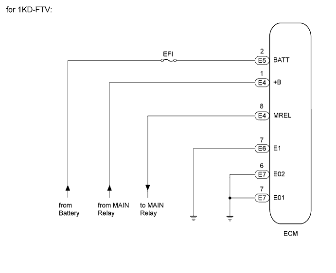
for 1KD-FTV:
Disconnect the E4, E5, E6 and E7 ECM connectors.
Measure the resistance according to the value(s) in the table below.
- Standard Resistance:
Tester Connection
| Condition
| Specified Condition
|
E6-7 (E1) - Body ground
| Always
| Below 1 Ω
|
E7-6 (E02) - Body ground
| Always
| Below 1 Ω
|
E7-7 (E01) - Body ground
| Always
| Below 1 Ω
|
Measure the voltage according to the value(s) in the table below.
- Standard Voltage:
Tester Connection
| Switch Condition
| Specified Condition
|
E4-1 (+B) - Body ground
| When battery's positive (+) voltage is applied to terminal E4-8 (MREL)
| 11 to 14 V
|
E5-2 (BATT) - Body ground
| Always
| 11 to 14 V
|
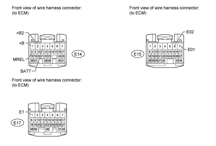
for 1GR-FE:
Disconnect the E14, E15 and E17 ECM connectors.
Measure the resistance according to the value(s) in the table below.
- Standard Resistance:
Tester Connection
| Condition
| Specified Condition
|
E17-1 (E1) - Body ground
| Always
| Below 1 Ω
|
E15-6 (E02) - Body ground
| Always
| Below 1 Ω
|
E15-7 (E01) - Body ground
| Always
| Below 1 Ω
|
Measure the voltage according to the value(s) in the table below.
- Standard Voltage:
Tester Connection
| Switch Condition
| Specified Condition
|
E14-1 (+B) - Body ground
| When battery's positive (+) voltage is applied to terminal E14-8 (MREL)
| 11 to 14 V
|
E14-2 (+B2) - Body ground
| When battery's positive (+) voltage is applied to terminal E14-8 (MREL)
| 11 to 14 V
|
E14-3 (BATT) - Body ground
| Always
| 11 to 14 V
|
ResultResult
| Proceed to
|
OK (for 1KD-FTV)
| A
|
OK (for 1GR-FE)
| B
|
NG
| C
|
| |
|
| | REPAIR OR REPLACE HARNESS OR CONNECTOR |
|
|