Ecd System Injector Circuit
DESCRIPTION
WIRING DIAGRAM
INSPECTION PROCEDURE
CHECK INJECTOR DRIVER (POWER SOURCE)
INSPECT NO. 1 INTEGRATION RELAY (EDU)
CHECK HARNESS AND CONNECTOR (NO. 1 INTEGRATION RELAY [EDU] - INJECTOR DRIVER)
CHECK HARNESS AND CONNECTOR (NO. 1 INTEGRATION RELAY - ECM)
ECD SYSTEM - Injector Circuit |
DESCRIPTION
The injector driver drives the injectors at high speeds with a high-voltage DC/DC converter. The ECM constantly monitors the injector driver and stops the engine if an abnormal condition is detected.
WIRING DIAGRAM
Refer to DTC P0200 (Toyota Fortuner RM00000187V034X_06.html).
INSPECTION PROCEDURE
- NOTICE:
- After replacing the ECM, the new ECM needs registration (Toyota Fortuner RM0000012XK04AX.html) and initialization (Toyota Fortuner RM000000TIN04KX.html).
- Inspect the fuses of circuits related to this system before performing the following inspection procedure.
| 1.CHECK INJECTOR DRIVER (POWER SOURCE) |
Disconnect the injector driver connectors.
Measure the voltage according to the value(s) in the table below.
- Standard Voltage:
Tester Connection
| Switch Condition
| Specified Condition
|
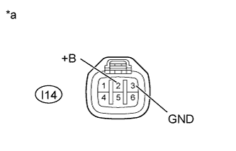
I14-2 (+B) - I14-3 (GND)
| Ignition switch ON
| 11 to 14 V
|
Text in Illustration*a
| Front view of wire harness connector
(to Injector Driver)
|
Reconnect the injector driver connector.
| 2.INSPECT NO. 1 INTEGRATION RELAY (EDU) |
Inspect the No. 1 integration relay (EDU) (Toyota Fortuner RM0000014TJ02IX.html).
| | REPLACE NO. 1 INTEGRATION RELAY (EDU) |
|
|
| 3.CHECK HARNESS AND CONNECTOR (NO. 1 INTEGRATION RELAY [EDU] - INJECTOR DRIVER) |
Remove the No. 1 integration relay from the engine room relay block and junction block assembly.
Disconnect the injector driver connector.
Measure the resistance according to the value(s) in the table below.
- Standard Resistance:
Tester Connection
| Condition
| Specified Condition
|
I14-2 (+B) - 1J-8
| Always
| Below 1 Ω
|
I14-3 (GND) - Body ground
| Always
| Below 1 Ω
|
I14-2 (+B) or 1J-8 - Body ground
| Always
| 10 kΩ or higher
|
Reconnect the No. 1 injector driver connector.
Reinstall the integration relay.
| | REPAIR OR REPLACE HARNESS OR CONNECTOR |
|
|
| 4.CHECK HARNESS AND CONNECTOR (NO. 1 INTEGRATION RELAY - ECM) |
Remove the No. 1 integration relay from the engine room relay block and junction block assembly.
Disconnect the ECM connector.
Measure the resistance according to the value(s) in the table below.
- Standard Resistance:
Tester Connection
| Condition
| Specified Condition
|
E4-10 (IREL) - 1J-7
| Always
| Below 1 Ω
|
E4-10 (IREL) or 1J-7 - Body ground
| Always
| 10 kΩ or higher
|
Reconnect the ECM connector.
Reinstall the No. 1 integration relay.
| | REPAIR OR REPLACE HARNESS OR CONNECTOR |
|
|