Air Conditioning System (For Automatic Air Conditioning System) Back-Up Power Source Circuit
DESCRIPTION
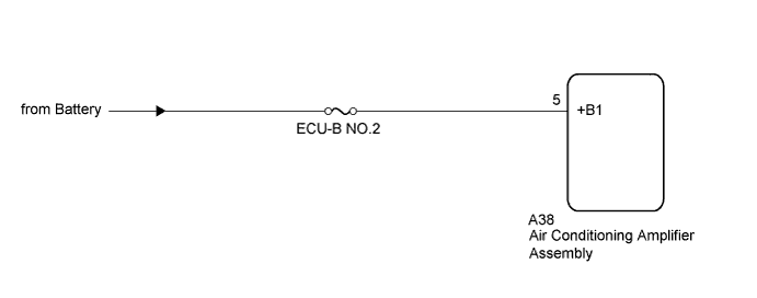
WIRING DIAGRAM
INSPECTION PROCEDURE
CHECK HARNESS AND CONNECTOR (AIR CONDITIONING AMPLIFIER - BATTERY)
AIR CONDITIONING SYSTEM (for Automatic Air Conditioning System) - Back-up Power Source Circuit |
DESCRIPTION
The back-up power source circuit for the air conditioning amplifier assembly is shown below. Power is supplied even after the ignition switch is turned off and is used for diagnostic trouble code memory, etc.
WIRING DIAGRAM
INSPECTION PROCEDURE
- NOTICE:
- Inspect the fuses for circuits related to this system before performing the following inspection procedure.
| 1.CHECK HARNESS AND CONNECTOR (AIR CONDITIONING AMPLIFIER - BATTERY) |
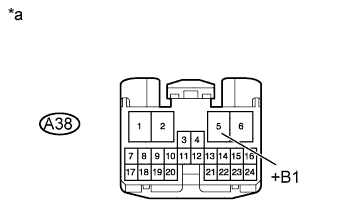
Disconnect the A38 air conditioning amplifier assembly connector.
Measure the voltage according to the value(s) in the table below.
- Standard Voltage:
Tester Connection
| Condition
| Specified Condition
|
A38-5 (+B1) - Body ground
| Always
| 11 to 14 V
|
Text in Illustration*a
| Front view of wire harness connector
(to Air Conditioning Amplifier Assembly)
|
| | REPAIR OR REPLACE HARNESS OR CONNECTOR |
|
|