Air Conditioning System (For Automatic Air Conditioning System) Vehicle Speed Signal Circuit
DESCRIPTION
WIRING DIAGRAM
INSPECTION PROCEDURE
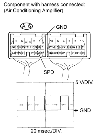
CHECK AIR CONDITIONING AMPLIFIER ASSEMBLY (SPD VOLTAGE)
CHECK HARNESS AND CONNECTOR (COMBINATION METER - AIR CONDITIONING AMPLIFIER)
AIR CONDITIONING SYSTEM (for Automatic Air Conditioning System) - Vehicle Speed Signal Circuit |
- HINT:
- Check that the speedometer in the combination meter operates normally before inspecting the vehicle speed signal circuit.
DESCRIPTION
The air conditioning amplifier monitors signals from the vehicle speed sensor via the combination meter. The air conditioning amplifier uses these signals to adjust the thermistor (A/C ambient temperature sensor) signal.If the speedometer does not operate normally, troubleshoot the meter/gauge system (Toyota Fortuner RM0000011IT012X.html).
WIRING DIAGRAM
INSPECTION PROCEDURE
| 1.CHECK AIR CONDITIONING AMPLIFIER ASSEMBLY (SPD VOLTAGE) |
Remove the air conditioning amplifier with its connectors still connected.
Move the shift lever to N.
Raise the vehicle.
Turn the ignition switch to ON.
Using an oscilloscope, check the waveform of the amplifier.
Measurement ConditionItem
| Content
|
Tester Connection
| A16-9 (SPD) - A16-1 (GND)
|
Tool Setting
| 5 V/DIV., 20 msec./DIV.
|
Condition
| Engine is running and speedometer indicates speed of 20 km/h (12 mph)
|
- OK:
- Waveform is as shown in the illustration.
- HINT:
- As the vehicle speed increases, the wavelength becomes shorter.
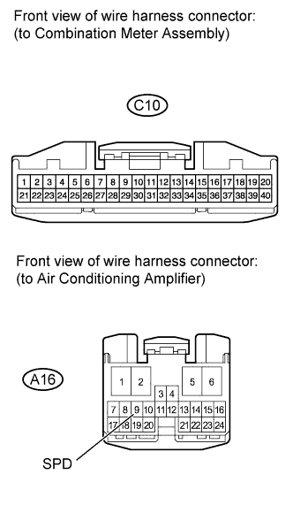
| 2.CHECK HARNESS AND CONNECTOR (COMBINATION METER - AIR CONDITIONING AMPLIFIER) |
Disconnect the C10 meter connector.
Disconnect the A16 amplifier connector.
Measure the resistance according to the value(s) in the table below.
- Standard Resistance:
Tester Connection
| Condition
| Specified Condition
|
C10-6 - A16-9 (SPD)
| Always
| Below 1 Ω
|
A16-9 (SPD) - Body ground
| Always
| 10 kΩ or higher
|
| | REPAIR OR REPLACE HARNESS OR CONNECTOR |
|
|