Ecd System -- System Description |
| ENGINE CONTROL SYSTEM |

| COMMON RAIL SYSTEM DESCRIPTION |
- The common rail system uses high-pressure fuel to improve fuel economy and to provide robust engine power, while suppressing engine vibration and noise.
This system stores fuel, which has been pressurized and supplied by the supply pump, in the common rail. By storing fuel at high-pressure, the common rail system can provide fuel at stable fuel injection pressures, regardless of engine speed or engine load.
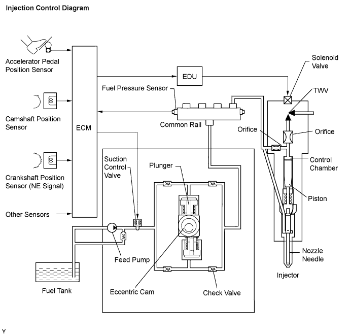
The ECM regulates the fuel injection timing and volume by using the EDU to provide an electric current to the solenoid valve in the injector. The ECM also monitors the internal fuel pressure of the common rail using the fuel pressure sensor. The ECM causes the supply pump to supply the fuel necessary to obtain the target fuel pressure.
In addition, this system has a 2-Way Valve (TWV) inside the injector to open and close the fuel passage. As a result, both fuel injection timing and fuel injection volume can be precisely regulated by the ECM.
The common rail system provides two split fuel injections. In order to soften combustion shock, this system performs "pilot-injection" as the subsidiary fuel injection prior to the main fuel injection. This helps to reduce engine vibration and noise.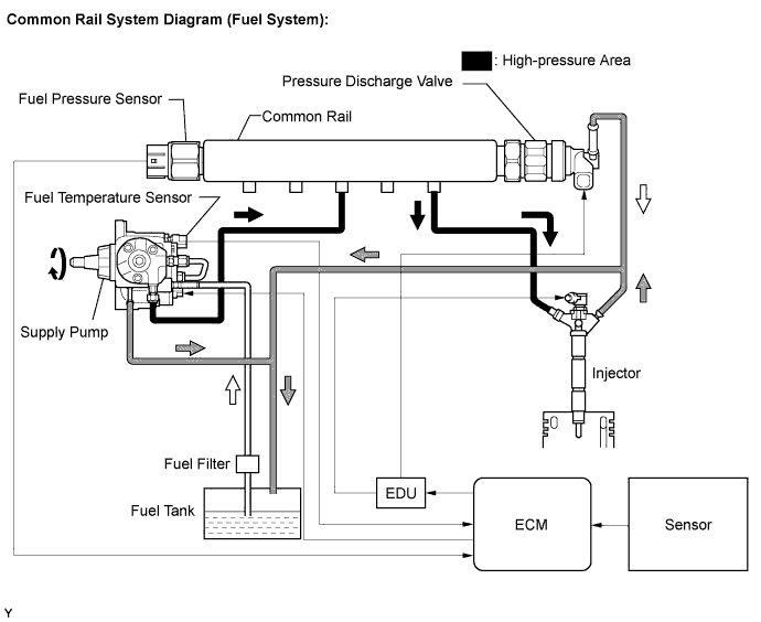
COMMON RAIL SYSTEM COMPONENTS: Component Description Common rail Stores high-pressure fuel produced by supply pump Supply pump Operated by crankshaft. Supplies high-pressure fuel to common rail. Injector Injects fuel to combustion chamber based on signals from ECM Fuel pressure sensor Monitors internal fuel pressure of common rail and sends signals to ECM Pressure discharge valve Based on signals from the ECM, opens valve when sudden deceleration is occurred, or when the ignition switch is OFF to prevent the fuel pressure from becoming too high. Suction control valve Based on signals from ECM, adjusts fuel volume supplied to common rail and regulates internal fuel pressure
- HINT:
- This table indicates typical DTC combinations for each malfunction occurrence.
Trouble Area Malfunction DTC No. Injector Open or short in injector circuit P0200, P0093* Stuck open P0093 Stuck closed - Fuel pressure sensor Open or short in fuel pressure sensor circuit or pressure sensor output fixed P0087, P0190, P0191, P0192, P0193 Pressure discharge valve Open or short in pressure discharge valve circuit P1271, P1272, P0088*, P0093*, P1229* Stuck open P0093 Stuck closed P1272, P0088* Suction control valve Open or short in suction control valve circuit P0627, P1229, P0088* Stuck open P1229, P0088* Stuck closed - EDU Faulty EDU P0093*, P0200*, P1271*, P1272* Common rail system (Fuel system) Fuel leaks in high-pressure areas P0093 - HINT:
- *: There may be no DTC output depending on the condition of the malfunction.
| DTC No. | Description | |
| P0087 | Fuel pressure sensor output does not change | |
| P0088 | Internal fuel pressure too high (200000 kPa [2039 kgf/cm2, 29007 psi] or more) | |
| P0093 | Fuel leaks in high-pressure areas | |
| P0190 | Open or short in fuel pressure sensor circuit (Low or high output) | |
| P0191 | Fuel pressure sensor out of range (Low output) | |
| P0192 | Open or short in fuel pressure sensor circuit (High output) | |
| P0193 | Open or short in fuel pressure sensor circuit (Sensor 1 and/or 2 relation) | |
| P0200 | Open or short in EDU or injector circuit | |
| P0627 | Open or short in suction control valve circuit | |
| P1229 | Fuel over-feed | |
| P1271 | Open or short in pressure discharge valve circuit | |
| P1272 | Closed malfunction of the pressure discharge valve | |
| INJECTION CONTROL SYSTEM DESCRIPTION |
The feed pump is used to pump fuel from the fuel tank to the supply pump.
| SUPPLY PUMP OPERATION SYSTEM DESCRIPTION |

| SUCTION CONTROL VALVE OPERATION SYSTEM DESCRIPTION |
- HINT:
- The ECM controls the suction control valve operation to regulate the fuel volume that is pumped by the supply pump to the common rail. This control is performed to adjust the internal fuel pressure of the common rail to the targeted injection pressure.
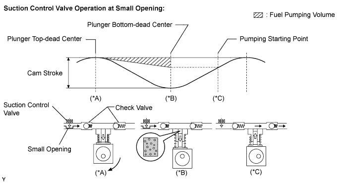
Small opening of the suction control valve:
When the opening of the suction control valve is small, the fuel suction path is kept narrow. Therefore the transferable fuel volume is reduced (*A).
The suction volume becomes small due to the narrow path despite the plunger stroke being full. The difference between the geometrical volume and suction volume creates a vacuum (*B).
Pumping will start when the fuel pressure becomes higher than the common rail pressure (*C).
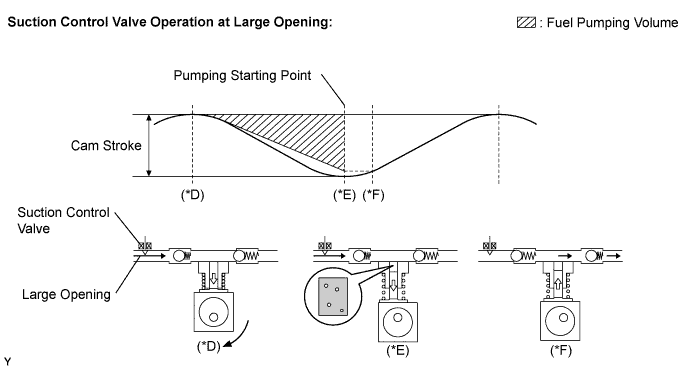
Large opening of the suction control valve:
When the opening of the suction control valve is large, the fuel suction path is kept wide. Therefore the transferable fuel volume is increased (*D).
If the plunger stroke is full, the suction volume becomes large because of the wide path (*E).
Pumping will start when the fuel pressure becomes higher than the common rail pressure (*F).