Audio And Visual System Radio Receiver Power Source Circuit
DESCRIPTION
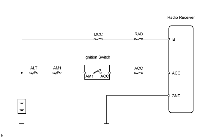
WIRING DIAGRAM
INSPECTION PROCEDURE
INSPECT FUSE (DCC, RAD, ACC)
CHECK WIRE HARNESS (RADIO RECEIVER - BATTERY AND BODY GROUND)
AUDIO AND VISUAL SYSTEM - Radio Receiver Power Source Circuit |
DESCRIPTION
This circuit provides power to the radio receiver.
WIRING DIAGRAM
INSPECTION PROCEDURE
| 1.INSPECT FUSE (DCC, RAD, ACC) |
Remove the ACC fuse from the instrument panel junction block.
Remove the DCC and RAD fuses from the engine room relay block.
Measure the resistance of the fuses.
- Standard resistance:
- Below 1 Ω
| 2.CHECK WIRE HARNESS (RADIO RECEIVER - BATTERY AND BODY GROUND) |
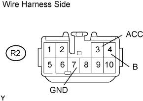
Disconnect the R2 receiver connector.
Measure the voltage and resistance of the wire harness side connector.
- Standard voltage:
Tester Connection
| Condition
| Specified Condition
|
R2-4 (B) - Body ground
| Always
| 10 to 14 V
|
R2-3 (ACC) - Body ground
| Ignition switch ACC
| 10 to 14 V
|
- Standard resistance:
Tester Connection
| Specified Condition
|
R2-7 (GND) - Body ground
| Below 1 Ω
|
| | REPAIR OR REPLACE HARNESS AND CONNECTOR |
|
|
| OK |
|
|
|
| REPLACE RADIO RECEIVER ASSEMBLY |
|