Dtc P0016/18 Crankshaft Position - Camshaft Position Correlation (Bank 1 Sensor A)
DESCRIPTION
MONITOR DESCRIPTION
INSPECTION PROCEDURE
CHECK VALVE TIMING (FOR LOOSENESS AND A JUMPED TOOTH OF TIMING CHAIN)
DTC P0016/18 Crankshaft Position - Camshaft Position Correlation (Bank 1 Sensor A) |
DESCRIPTION
In the VVT system, the appropriate intake valve open and close timing is controlled by the ECM. The ECM performs intake valve control by performing the following: 1) controlling the camshaft and camshaft oil control valve, and operating the camshaft timing gear; and 2) changing the relative positions of the gaps between the camshaft and crankshaft.Refer to DTCs P0335/13 and P0339/13 (Toyota Fortuner RM000000ZQI006X_01.html). DTC No.
| DTC Detection Condition
| Trouble Area
|
P0016/18
| Deviation in crankshaft position sensor signal and camshaft position signal (2 trip detection logic)
| - Mechanical system (jumped tooth of timing chain or chain stretched)
- ECM
|
MONITOR DESCRIPTION
To monitor the correlation of the intake camshaft position and crankshaft position, the ECM checks the VVT learning value while the engine is idling. The VVT learning value is calibrated based on the camshaft position and crankshaft position. The intake valve timing is set to the most retarded angle while the engine is idling. If the VVT learning value is out of specified range in consecutive driving cycles, the ECM illuminates the MIL and sets the DTC P0016/18.
INSPECTION PROCEDURE
- HINT:
- Read freeze frame data using the intelligent tester. Freeze frame data records the engine conditions when malfunctions are detected. When troubleshooting, freeze frame data can help determine if the vehicle was moving or stationary, if the engine was warmed up or not, if the air-fuel ratio was lean or rich, and other data from the time the malfunction occurred.
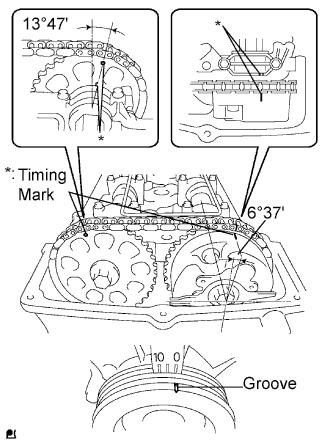
| 1.CHECK VALVE TIMING (FOR LOOSENESS AND A JUMPED TOOTH OF TIMING CHAIN) |
Remove the cylinder head cover.
Turn the crankshaft to align the timing marks of the crankshaft.
Align the groove of the crankshaft pulley with the "0" position.
Confirm whether the timing marks of the camshaft pulley and cylinder head cover are facing each other.
If the timing marks are not facing each other, turn the crankshaft clockwise by 360°. Confirm again if the timing marks are facing each other.
- OK:
- The timing marks of the camshaft pulley and the cylinder head cover face each other when the groove of the crankshaft pulley is in the "0" position.
| | ADJUST VALVE TIMING (REPAIR OR REPLACE TIMING CHAIN) |
|
|