Ecd System Air Conditioning Signal Circuit
DESCRIPTION
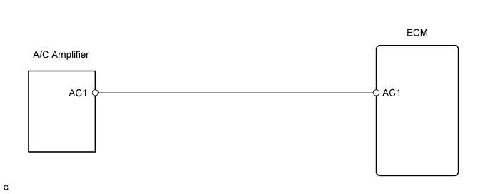
WIRING DIAGRAM
INSPECTION PROCEDURE
When using intelligent tester:
READ VALUE USING INTELLIGENT TESTER (AIR CONDITIONING SIGNAL)
CHECK ECM (AC1 VOLTAGE)
CHECK HARNESS AND CONNECTOR (ECM - AIR CONDITIONING AMPLIFIER)
When not using intelligent tester:
CHECK ECM (AC1 VOLTAGE)
CHECK HARNESS AND CONNECTOR (ECM - AIR CONDITIONING AMPLIFIER)
ECD SYSTEM - Air Conditioning Signal Circuit |
DESCRIPTION
When the A/C compressor is on, the A/C amplifier sends the A/C signal to the ECM, then the ECM increases the fuel injection volume to improve driveability during engine idling.
WIRING DIAGRAM
INSPECTION PROCEDURE
When using intelligent tester:
| 1.READ VALUE USING INTELLIGENT TESTER (AIR CONDITIONING SIGNAL) |
Connect the intelligent tester to the DLC3.
Start the engine.
Turn the A/C switch ON.
Enter the following menus: Powertrain / Engine and ECT / Data List / A/C SIG.
- Result:
A/C Compressor
| Display
|
OFF
| A/C SIG OFF
|
ON
| A/C SIG ON
|
| | PROCEED TO NEXT CIRCUIT INSPECTION SHOWN IN PROBLEM SYMPTOMS TABLE |
|
|
| 2.CHECK ECM (AC1 VOLTAGE) |
Start the engine.
Measure the voltage of the ECM connector.
- Standard voltage:
Tester Connection
| Condition
| Specified Condition
|
E22-2 (AC1) - Body ground
| A/C compressor ON
| Below 1.5 V
|
E22-2 (AC1) - Body ground
| A/C compressor OFF
| 7.5 to 14 V
|
| 3.CHECK HARNESS AND CONNECTOR (ECM - AIR CONDITIONING AMPLIFIER) |
Disconnect the A14 A/C amplifier connector.
Disconnect the E22 ECM connector.
Measure the resistance of the wire harness side connectors.
- Standard resistance:
Tester Connection
| Specified Condition
|
A14-14 (AC1)* - E22-2 (AC1)
| Below 1 Ω
|
E22-2 (AC1) - Body ground
| 10 kΩ or higher
|
- HINT:
- *: Terminal arrangement (Toyota Fortuner RM000002HPK000X.html).
| | REPAIR OR REPLACE HARNESS OR CONNECTOR |
|
|
| OK |
|
|
|
| REPLACE AIR CONDITIONING AMPLIFIER |
|
When not using intelligent tester:
| 1.CHECK ECM (AC1 VOLTAGE) |
Start the engine.
Measure the voltage of the ECM connector.
- Standard voltage:
Tester Connection
| Condition
| Specified Condition
|
E22-2 (AC1) - Body ground
| A/C compressor ON
| Below 1.5 V
|
E22-2 (AC1) - Body ground
| A/C compressor OFF
| 7.5 to 14 V
|
| | PROCEED TO NEXT CIRCUIT INSPECTION SHOWN IN PROBLEM SYMPTOMS TABLE |
|
|
| 2.CHECK HARNESS AND CONNECTOR (ECM - AIR CONDITIONING AMPLIFIER) |
Disconnect the A14 A/C amplifier connector.
Disconnect the E22 ECM connector.
Measure the resistance of the wire harness side connectors.
- Standard resistance:
Tester Connection
| Specified Condition
|
A14-4 (AC1)* - E22-2 (AC1)
| Below 1 Ω
|
E22-2 (AC1) - Body ground
| 10 kΩ or higher
|
- HINT:
- *: Terminal arrangement (Toyota Fortuner RM000002HPK000X.html).
| | REPAIR OR REPLACE HARNESS OR CONNECTOR |
|
|
| OK |
|
|
|
| REPLACE AIR CONDITIONING AMPLIFIER |
|