Ecd System Starter Signal Circuit
DESCRIPTION
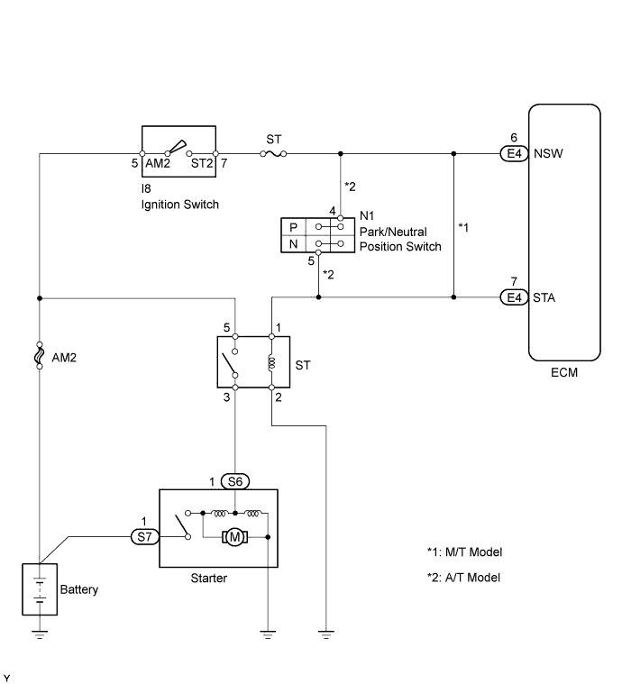
WIRING DIAGRAM
INSPECTION PROCEDURE
READ VALUE USING INTELLIGENT TESTER (STARTER SIG)
CHECK WIRE HARNESS (ECM - STARTER RELAY (Marking: ST))
ECD SYSTEM - Starter Signal Circuit |
DESCRIPTION
While the engine is being cranked, current flows from terminal ST2 of the ignition switch to the ST fuse and also flows to terminal STA of the ECM (STA signal).
WIRING DIAGRAM
INSPECTION PROCEDURE
- HINT:
- This chart is based on the premise that the engine can crank normally. If the engine cannot crank normally, proceed to the problem symptoms table (Toyota Fortuner RM0000012WF044X.html).
- NOTICE:
- If the ECM is replaced, the new ECM needs initialization (Toyota Fortuner RM000000TIN04NX.html).
| 1.READ VALUE USING INTELLIGENT TESTER (STARTER SIG) |
Connect the intelligent tester to the DLC3.
Turn the ignition switch ON and turn the intelligent tester ON.
Enter the following menus: Powertrain / Engine and ECT / Data List / Starter Signal.
Read the values.
- OK:
Ignition Switch Position
| Starter SIG
|
ON
| OFF
|
START
| ON
|
| | PROCEED TO NEXT CIRCUIT INSPECTION SHOWN IN PROBLEM SYMPTOMS TABLE |
|
|
| 2.CHECK WIRE HARNESS (ECM - STARTER RELAY (Marking: ST)) |
Disconnect the E4 ECM connector.
Remove the starter relay from the engine room relay block.
Measure the resistance of the wire harness side connectors.
- Standard resistance :
Tester Connection
| Specified Condition
|
Relay block starter relay terminal 1 - E4-7 (STA)
| Below 1 Ω
|
Relay block starter relay terminal 1 or E4-7 (STA) - Body ground
| 10 kΩ or higher
|
| | REPAIR OR REPLACE HARNESS AND CONNECTOR |
|
|