Cruise Control System Cruise Control Switch Circuit
DESCRIPTION
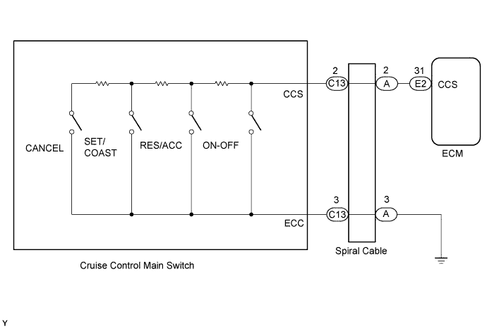
WIRING DIAGRAM
INSPECTION PROCEDURE
READ VALUE USING DATA LIST (CRUISE CONTROL MAIN SWITCH)
INSPECT CRUISE CONTROL MAIN SWITCH
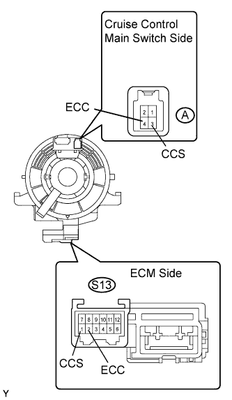
INSPECT SPIRAL CABLE
CHECK WIRE HARNESS (SPIRAL CABLE - ECM AND BODY GROUND)
CRUISE CONTROL SYSTEM - Cruise Control Switch Circuit |
DESCRIPTION
This circuit sends signals to the ECM depending on the cruise control main switch condition. The battery supplies positive (+) battery voltage to the cruise control main switch. Then terminal CCS of the ECM receives the voltage according to the switch condition.
WIRING DIAGRAM
INSPECTION PROCEDURE
| 1.READ VALUE USING DATA LIST (CRUISE CONTROL MAIN SWITCH) |
Connect the intelligent tester to the DLC3.
Turn the ignition switch ON and turn the intelligent tester main switch ON.
Check the Data List for proper functioning of the cruise control main switch.
ECM (Cruise control):Item
| Measurement Item / Display (Range)
| Normal Condition
| Diagnostic Note
|
Main SW M-CPU
| Cruise control main switch signal (Main CPU) / ON or OFF
| ON: Cruise control main switch is ON (Main CPU)
OFF: Cruise control main switch is OFF (Main CPU)
| -
|
Main SW M-CPU
| Cruise control main switch signal (Main CPU) / ON or OFF
| ON: Cruise control main switch is ON (Sub CPU)
OFF: Cruise control main switch is OFF (Sub CPU)
| -
|
Cancel Switch
| CANCEL switch signal / ON or OFF
| ON: CANCEL switch ON
OFF: CANCEL switch OFF
| -
|
SET/COAST Switch
| SET/COAST switch signal / ON or OFF
| ON: SET/COAST switch ON
OFF: SET/COAST switch OFF
| -
|
RES/ACC Switch
| RES/ACC switch signal / ON or OFF
| ON: RES/ACC switch ON
OFF: RES/ACC switch OFF
| -
|
- OK:
- When cruise control main switch operation is performed, results will be same as above.
| | PROCEED TO NEXT CIRCUIT INSPECTION SHOWN IN PROBLEM SYMPTOMS TABLE |
|
|
| 2.INSPECT CRUISE CONTROL MAIN SWITCH |
Disconnect the cruise control main switch connector.
Measure the resistance of the switch.
- Standard resistance:
Tester Connection
| Switch Condition
| Specified Condition
|
3 - 4
| RES/ACC
| 216 to 264 Ω
|
3 - 4
| SET/COAST
| 567 to 693 Ω
|
3 - 4
| CANCEL
| 1,386 to 1,694 Ω
|
3 - 4
| Main switch OFF
| 10 kΩ or higher
|
3 - 4
| Main switch ON
| Below 1 Ω
|
| | REPLACE CRUISE CONTROL MAIN SWITCH ASSEMBLY |
|
|
Disconnect the S13 cable connector.
Disconnect the cruise control main switch connector.
Measure the resistance of the spiral cable.
- Standard resistance:
Tester Connection
| Specified Condition
|
A-3 (CCS) - S13-1 (CCS)
| Below 1 Ω
|
A-4 (ECC) - S13-2 (ECC)
| Below 1 Ω
|
| | REPLACE SPIRAL CABLE SUB-ASSEMBLY |
|
|
| 4.CHECK WIRE HARNESS (SPIRAL CABLE - ECM AND BODY GROUND) |
Disconnect the S13 cable connector.
Disconnect the E13 ECM connector.
Measure the resistance of the wire harness side connectors.
- Standard resistance:
Tester Connection
| Specified Condition
|
S13-1 (CCS) - E13-2 (CCS)
| Below 1 Ω
|
S13-2 (ECC) - Body ground
| Below 1 Ω
|
S13-1 (CCS) - Body ground
| 10 kΩ or higher
|
| | REPAIR OR REPLACE WIRE HARNESS AND CONNECTOR |
|
|
| OK |
|
|
|
| PROCEED TO NEXT CIRCUIT INSPECTION SHOWN IN PROBLEM SYMPTOMS TABLE |
|