Cruise Control System -- Terminals Of Ecu |
| CHECK ECM (for 1GR-FE) |

Disconnect the E14, E15 and E17 ECM connectors.
Measure the voltage and resistance according to the value(s) in the table below.
If the result is not as specified, there may be a malfunction on the wire harness side.Terminal No. (Symbol) Wiring Color Terminal Description Condition Specified Condition E14-3 (BATT) - E17-1 (E1) L - BR Battery Always 11 to 14 V E14-9 (IGSW) - E17-1 (E1) B-O - BR IG power supply Ignition switch ON 11 to 14 V E14-9 (IGSW) - E17-1 (E1) B-O - BR IG power supply Ignition switch off Below 1 V E17-1 (E1) - Body ground BR - Body ground Ground Always Below 1 Ω E15-28 (E2) - Body ground BR - Body ground Ground Always Below 1 Ω Reconnect the E14, E15 and E17 ECM connectors.
Measure the voltage according to the value(s) in the table below.
If the result is not as specified, the ECM may have a malfunction.Terminal No. (Symbol) Wiring Color Terminal Description Condition Specified Condition E14-15 (STP) - E17-1 (E1) G-W - BR Stop light switch input signal Ignition switch ON
Brake pedal releasedBelow 1 V E14-15 (STP) - E17-1 (E1) G-W - BR Stop light switch input signal Ignition switch ON
Brake pedal depressed11 to 14 V E14-16 (ST1-) - E17-1 (E1) R-L - BR Cruise cancel input signal Ignition switch ON
Brake pedal depressedBelow 1 V E14-16 (ST1-) - E17-1 (E1) R-L - BR Cruise cancel input signal Ignition switch ON
Brake pedal released11 to 14 V E13-2 (CCS) - E17-1 (E1) G-W - BR Cruise control main switch signal Ignition switch ON 11 to 14 V E13-2 (CCS) - E17-1 (E1) G-W - BR Cruise control main switch signal Ignition switch ON
CANCEL switch held on6.6 to 10.1 V E13-2 (CCS) - E17-1 (E1) G-W - BR Cruise control main switch signal Ignition switch ON
-SET switch held on4.5 to 7.1 V E13-2 (CCS) - E17-1 (E1) G-W - BR Cruise control main switch signal Ignition switch ON
+RES switch held on2.3 to 4.0 V E13-2 (CCS) - E17-1 (E1) G-W - BR Cruise control main switch signal Ignition switch ON
Main switch onBelow 1 V E13-18 (PI) - E17-1 (E1) L-B - BR Cruise main indicator light input signal Ignition switch ON
Main switch onBelow 1 V E13-18 (PI) - E17-1 (E1) L-B - BR Cruise control main switch signal Ignition switch ON
Main switch off11 to 14 V E14-23 (TC) - E17-1 (E1) P-B - BR Terminal TC of DLC3 Ignition switch ON 9 to 14 V
| CHECK ECM (for 1KD-FTV) |
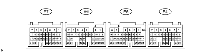
Disconnect the E4, E5, E6 and E7 ECM connectors.
Measure the voltage and resistance according to the value(s) in the table below.
If the result is not as specified, there may be a malfunction on the wire harness side.Terminal No. (Symbol) Wiring Color Terminal Description Condition Specified Condition E5-2 (BATT) - E6-7 (E1) L - BR Battery Always 11 to 14 V E4-9 (IGSW) - E6-7 (E1) B-O - BR IG power supply Ignition switch ON 11 to 14 V E4-9 (IGSW) - E6-7 (E1) B-O - BR IG power supply Ignition switch off Below 1 V E6-7 (E1) - Body ground BR - Body ground Ground Always Below 1 Ω E7-28 (E2) - Body ground BR - Body ground Ground Always Below 1 Ω Reconnect the E4, E5, E6 and E7 ECM connectors.
Measure the voltage according to the value(s) in the table below.
*: for Manual TransmissionTerminal No. (Symbol) Wiring Color Terminal Description Condition Specified Condition E5-15 (STP) - E6-7 (E1) G-W - BR Stop light switch input signal Ignition switch ON
Brake pedal releasedBelow 1 V E5-15 (STP) - E6-7 (E1) G-W - BR Stop light switch input signal Ignition switch ON
Brake pedal depressed11 to 14 V E5-14 (ST1-) - E6-7 (E1) R-L - BR Cruise cancel input signal Ignition switch ON
Brake pedal depressedBelow 1 V E5-14 (ST1-) - E6-7 (E1) R-L - BR Cruise cancel input signal Ignition switch ON
Brake pedal released11 to 14 V E4-21 (CCS) - E6-7 (E1) G-W - BR Cruise control main switch signal Ignition switch ON 11 to 14 V E4-21 (CCS) - E6-7 (E1) G-W - BR Cruise control main switch signal Ignition switch ON
CANCEL switch held on6.6 to 10.1 V E4-21 (CCS) - E6-7 (E1) G-W - BR Cruise control main switch signal Ignition switch ON
-SET switch held on4.5 to 7.1 V E4-21 (CCS) - E6-7 (E1) G-W - BR Cruise control main switch signal Ignition switch ON
+RES switch held on2.3 to 4.0 V E4-21 (CCS) - E6-7 (E1) G-W - BR Cruise control main switch signal Ignition switch ON
Main switch onBelow 1 V E5-3 (PI) - E6-7 (E1) L-B - BR Cruise main indicator light input signal Ignition switch ON
Main switch onBelow 1 V E5-3 (PI) - E6-7 (E1) L-B - BR Cruise control main switch signal Ignition switch ON
Main switch off11 to 14 V E5-10 (CLSW) - E6-7 (E1)* G-W - BR Clutch signal Ignition switch ON
Clutch pedal released11 to 14 V E5-10 (CLSW) - E6-7 (E1)* G-W - BR Clutch signal Ignition switch ON
Clutch pedal depressedBelow 1 V E4-11 (TC) - E6-7 (E1) P-B - BR Terminal TC of DLC3 Ignition switch ON 9 to 14 V
If the result is not as specified, the ECM may have a malfunction.