Sfi System -- Terminals Of Ecm |
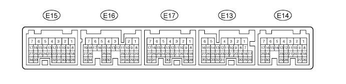
- HINT:
- Each ECM terminal's normal voltage is shown in the table below.
- In the table, first follow the information under "Condition". Look under "Symbols (Terminal No.)" for the terminals to be inspected. The standard voltage between the terminals is shown under "Specified Condition".
- Use the illustration above as a reference for the ECM terminals.
| Symbols (Terminal No.) | Wiring Color | Terminal Description | Condition | Specified Condition |
| BATT (E14-3) - E1 (E17-1) | L - BR | Battery (for measuring battery voltage and for ECM memory) | Always | 9 to 14 V |
| +BM (E14-7) - E1 (E17-1) | R-W - BR | Power source of throttle motor | Always | 9 to 14 V |
| IGSW (E14-9) - E1 (E17-1) | B-O - BR | Ignition switch | Ignition switch ON | 9 to 14 V |
| +B (E14-1) - E1 (E17-1) | B - BR | Power source of ECM | Ignition switch ON | 9 to 14 V |
| +B2 (E14-2) - E1 (E17-1) | B - BR | Power source of ECM | Ignition switch ON | 9 to 14 V |
| OC1+ (E17-17) - OC1- (E17-16) | L-B - R-B | Camshaft timing oil control valve (OCV) | Ignition switch ON | Pulse generation (see waveform 1) |
| OC2+ (E17-15) - OC2- (E17-14) | P-L - Y | Camshaft timing oil control valve (OCV) | Ignition switch ON | Pulse generation (see waveform 1) |
| MREL (E14-8) - E1 (E17-1) | W-G - BR | MAIN relay | Ignition switch ON | 9 to 14 V |
| VC (E15-23) - E2 (E15-28) | LG-B - BR | Power source for sensors (specific voltage) | Ignition switch ON | 4.5 to 5.5 V |
| VG (E15-30) - E2G (E15-29) | L-W - L-R | Mass air flow meter | Idling, Shift lever position P or N, A/C switch OFF | 0.5 to 3.0 V |
| THA (E15-22) - E2 (E15-28) | L-B - BR | Intake air temperature sensor | Idling, Intake air temperature 20°C (68°F) | 0.5 to 3.4 V |
| THW (E15-21) - E2 (E15-28) | B - BR | Engine coolant temperature sensor | Idling, Engine coolant temperature 80°C (176°F) | 0.2 to 1.0 V |
| VTA1 (E15-20) - E2 (E15-28) | B-R - BR | Throttle position sensor (for engine control) | Ignition switch ON, Throttle valve fully closed | 0.5 to 1.2 V |
| VTA1 (E15-20) - E2 (E15-28) | B-R - BR | Throttle position sensor (for engine control) | Ignition switch ON, Throttle valve fully open | 3.2 to 4.8 V |
| VTA2 (E15-19) - E2 (E15-28) | LG - BR | Throttle position sensor (for sensor malfunction detection) | Ignition switch ON, Accelerator pedal released | 2.1 to 3.1 V |
| VTA2 (E15-19) - E2 (E15-28) | LG - BR | Throttle position sensor (for sensor malfunction detection) | Ignition switch ON, Accelerator pedal depressed | 4.5 to 5.0 V |
| VPA (E14-18) - EPA (E14-20) | W-L - BR-W | Accelerator pedal position sensor (for engine control) | Ignition switch ON, Accelerator pedal released | 0.5 to 1.1 V |
| VPA (E14-18) - EPA (E14-20) | W-L - BR-W | Accelerator pedal position sensor (for engine control) | Ignition switch ON, Accelerator pedal depressed | 2.6 to 4.5 V |
| VPA2 (E14-19) - EPA2 (E14-21) | GR-G - BR-Y | Accelerator pedal position sensor (for sensor malfunctioning detection) | Ignition switch ON, Accelerator pedal released | 1.2 to 2.0 V |
| VPA2 (E14-19) - EPA2 (E14-21) | GR-G - BR-Y | Accelerator pedal position sensor (for sensor malfunctioning detection) | Ignition switch ON, Accelerator pedal depressed | 3.4 to 5.0 V |
| VCPA (E14-26) - EPA (E14-20) | LG-R - BR-W | Power source of accelerator pedal position sensor (for VPA) | Ignition switch ON | 4.5 to 5.5 V |
| VCP2 (E14-27) - EPA2 (E14-21) | BR-R - BR-Y | Power source of accelerator pedal position sensor (for VPA2) | Ignition switch ON | 4.5 to 5.5 V |
| HA1A (E16-2) - E04 (E16-7) | Y - W-B | A/F sensor heater | Idling | Pulse generation (see waveform 2) |
| HA2A (E16-1) - E05 (E16-6) | R-L - W-B | A/F sensor heater | Idling | Pulse generation (see waveform 2) |
| HA1A (E16-2) - E04 (E16-7) | Y - W-B | A/F sensor heater | Ignition switch ON | 9 to 14 V |
| HA2A (E16-1) - E05 (E16-6) | R-L - W-B | A/F sensor heater | Ignition switch ON | 9 to 14 V |
| A1A+ (E16-22) - E1 (E17-1) | B - BR | A/F sensor | Ignition switch ON | 3.3 V *1 |
| A2A+ (E16-23) - E1 (E17-1) | G - BR | A/F sensor | Ignition switch ON | 3.3 V *1 |
| A1A- (E16-30) - E1 (E17-1) | W - BR | A/F sensor | Ignition switch ON | 3.0 V *1 |
| A2A- (E16-31) - E1 (E17-1) | R - BR | A/F sensor | Ignition switch ON | 3.0 V *1 |
| HT1B (E15-1) - E1 (E17-1) | G - BR | Heated oxygen sensor heater | Idling | Below 3.0 V |
| HT2B (E16-5) - E1 (E17-1) | L - BR | Heated oxygen sensor heater | Idling | Below 3.0 V |
| HT1B (E15-1) - E1 (E17-1) | G - BR | Heated oxygen sensor heater | Ignition switch ON | 9 to 14 V |
| HT2B (E16-5) - E1 (E17-1) | L - BR | Heated oxygen sensor heater | Ignition switch ON | 9 to 14 V |
| OX1B (E15-18) - E2 (E15-28) | W - BR | Heated oxygen sensor | Maintain engine speed at 2,500 rpm for 2 minutes after warming up | Pulse generation (see waveform 3) |
| OX2B (E16-33) - E2 (E15-28) | B - BR | Heated oxygen sensor | Maintain engine speed at 2,500 rpm for 2 minutes after warming up | Pulse generation (see waveform 3) |
| #10 (E17-2) - E01 (E15-7) #20 (E17-3) - E01 (E15-7) #30 (E17-4) - E01 (E15-7) #40 (E17-5) - E01 (E15-7) #50 (E17-6) - E01 (E15-7) #60 (E17-7) - E01 (E15-7) | L - W-B G - W-B R - W-B W - W-B L - W-B Y - W-B | Injector | Ignition switch ON | 9 to 14 V |
| #10 (E17-2) - E01 (E15-7) #20 (E17-3) - E01 (E15-7) #30 (E17-4) - E01 (E15-7) #40 (E17-5) - E01 (E15-7) #50 (E17-6) - E01 (E15-7) #60 (E17-7) - E01 (E15-7) | L - W-B G - W-B R - W-B W - W-B L - W-B Y - W-B | Injector | Idling | Pulse generation (see waveform 4) |
| IGT1 (E15-8) - E1 (E17-1) | R - BR | Ignition coil (ignition signal) | Idling | Pulse generation (see waveform 7) |
| IGT2 (E15-9) - E1 (E17-1) | R-L - BR | Ignition coil (ignition signal) | Idling | Pulse generation (see waveform 7) |
| IGT3 (E15-10) - E1 (E17-1) | G-B - BR | Ignition coil (ignition signal) | Idling | Pulse generation (see waveform 7) |
| IGT4 (E15-11) - E1 (E17-1) | G - BR | Ignition coil (ignition signal) | Idling | Pulse generation (see waveform 7) |
| IGT5 (E15-12) - E1 (E17-1) | B-L - BR | Ignition coil (ignition signal) | Idling | Pulse generation (see waveform 7) |
| IGT6 (E15-13) - E1 (E17-1) | P-L - BR | Ignition coil (ignition signal) | Idling | Pulse generation (see waveform 7) |
| KNK1 (E16-29) - EKNK (E16-28) | B - W | Knock sensor | Maintain engine speed at 4,000 after warming up | Pulse generation (see waveform 5) |
| KNK2 (E16-21) - EKN2 (E16-20) | R - G | Knock sensor | Maintain engine speed at 4,000 after warming up | Pulse generation (see waveform 5) |
| VV1+ (E17-19) - VV1- (E17-29) | R - G | Variable valve timing (VVT) sensor | Idling | Pulse generation (see waveform 6) |
| VV2+ (E17-18) - VV2- (E17-28) | Y - L | Variable valve timing (VVT) sensor | Idling | Pulse generation (see waveform 6) |
| NE+ (E17-21) - NE- (E17-20) | B - W | Crankshaft position sensor | Idling | Pulse generation (see waveform 6) |
| IGF1 (E15-24) - E1 (E17-1) | G-R - BR | Ignition coil (ignition confirmation signal) | Ignition switch ON | 4.5 to 5.5 V |
| IGF1 (E15-24) - E1 (E17-1) | G-R - BR | Ignition coil (ignition confirmation signal) | Idling | Pulse generation (see waveform 7) |
| PRG (E15-34) - E1 (E17-1) | L - BR | Purge VSV | Ignition switch ON | 9 to 14 V |
| PRG (E15-34) - E1 (E17-1) | L - BR | Purge VSV | Idling | Pulse generation (see waveform 8) |
| SPD (E13-8) - E1 (E17-1) | V-R - BR | Speed signal from combination meter | Ignition switch ON, Rotate driving wheel slowly | Pulse generation (see waveform 9) |
| STA (E17-11) - E1 (E17-1) | B-Y - BR *2 L-Y - BR *3 | Starter signal | Cranking | 9 to 14 V |
| NSW (E16-8) - E1 (E17-1) | L-Y - BR | Park/Neutral position switch signal | Ignition switch ON, Other shift position not in P or N | 9 to 14 V |
| NSW (E16-8) - E1 (E17-1) | L-Y - BR | Park/Neutral position switch signal | Ignition switch ON, Shift position in P or N | 0 to 3.0 V |
| STP (E14-15) - E1 (E17-1) | G-W - BR | Stop light switch | Brake pedal depressed | 7.5 to 14 V |
| STP (E14-15) - E1 (E17-1) | G-W - BR | Stop light switch | Brake pedal released | Below 1.5 V |
| ST1- (E14-16) - E1 (E17-1) | R-L - BR | Stop light switch (ST1 terminal status is opposite to STP terminal) | Ignition switch ON, Brake pedal depressed | Below 1.5 V |
| ST1- (E14-16) - E1 (E17-1) | R-L - BR | Stop light switch (ST1 terminal status is opposite and STP terminal) | Ignition switch ON, Brake pedal released | 7.5 to 14 V |
| M+ (E15-5) - ME01 (E16-3) | B - W-B | Throttle actuator | Idling with warm engine | Pulse generation (see waveform 10) |
| M- (E15-4) - ME01 (E16-3) | W - W-B | Throttle actuator | Idling with warm engine | Pulse generation (see waveform 11) |
| FC (E14-10) - E1 (E17-1) | LG-B - BR | Fuel pump control | Ignition switch ON | 9 to 14 V |
| FPR (E17-30) - E1 (E17-1) | P-L - BR | Fuel pump control | Ignition switch ON, STA signal OFF | 0 to 3.0 V |
| FPR (E17-30) - E1 (E17-1) | P-L - BR | Fuel pump control | Ignition switch ON, STA signal ON | 9 to 14 V |
| W (E13-30) - E1 (E17-1) | R-B - BR | MIL | Ignition switch ON | Below 3.0 V |
| W (E13-30) - E1 (E17-1) | R-B - BR | MIL | Idling | 9 to 14 V |
| TC (E14-23) - E1 (E17-1) | P-B - BR | Terminal TC of DLC3 | Ignition switch ON | 9 to 14 V |
| SIL (E14-30) - E1 (E17-1) | R-Y - BR | Terminal SIL of DLC3 | Connect intelligent tester to DLC3 | Pulse generation |
| TACH (E13-1) - E1 (E17-1) | B-W - BR | Engine speed | Idling | Pulse generation (see waveform 12) |
| ACIS (E15-33) - E1 (E17-1) | G-B - BR | VSV for ACIS | Ignition switch ON | 9 to 14 V |
| PSW (E17-10) - E1 (E17-1) | G-Y - BR | Power steering pressure switch | Ignition switch ON | 9 to 14 V |
- HINT:
- *1: The ECM terminal voltage is constant regardless of the output voltage from the sensor.
- *2: A/T
- *3: M/T
| WAVEFORM 1 |
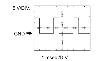 |
- Camshaft timing Oil Control Valve (OCV)
| Item | Content |
| Symbols (Terminal No.) | OC1+ (E17-17) - OC1- (E17-16) OC2+ (E17-15) - OC2- (E17-14) |
| Tool Setting | 5 V/DIV., 1 msec./DIV. |
| Condition | Idling |
- HINT:
- The wavelength becomes shorter as the engine rpm increases.
| WAVEFORM 2 |
 |
- A/F sensor heater
| Item | Content |
| Symbols (Terminal No.) | HA1A (E16-2) - E04 (E16-7) HA2A (E16-1) - E05 (E16-6) |
| Tool Setting | 5 V/DIV., 10 msec./DIV. |
| Condition | Idling |
| WAVEFORM 3 |
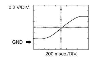 |
- Heated oxygen sensor
| Item | Content |
| Symbols (Terminal No.) | OX1B (E15-18) - E2 (E15-28) OX2B (E16-33) - E2 (E15-28) |
| Tool Setting | 0.2 V/DIV., 200 msec./DIV. |
| Condition | Engine speed maintained at 2,500 rpm for 2 minutes after warming up engine |
- HINT:
- In the Data List, item O2S B1S2 shows the ECM input values from the heated oxygen sensor.
| WAVEFORM 4 |
 |
- Fuel injector
| Item | Content |
| Symbols (Terminal No.) | #10 (E17-2) - E01 (E15-7) #20 (E17-3) - E01 (E15-7) #30 (E17-4) - E01 (E15-7) #40 (E17-5) - E01 (E15-7) #50 (E17-6) - E01 (E15-7) #60 (E17-7) - E01 (E15-7) |
| Tool Setting | 30 V/DIV., 20 msec./DIV. |
| Condition | Idling |
- HINT:
- The wavelength becomes shorter as the engine rpm increases.
| WAVEFORM 5 |
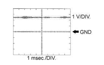 |
- Knock sensor
| Item | Content |
| Symbols (Terminal No.) | KNK1 (E16-29) - EKNK (E16-28) KNK2 (E16-21) - EKN2 (E16-20) |
| Tool Setting | 0.01 to 10 V/DIV., 0.01 to 10 msec./DIV. |
| Condition | Maintain engine speed at 4,000 rpm after warming up engine |
- HINT:
- The wavelength becomes shorter as the engine rpm increases.
- The waveform and amplitude displayed differ slightly depending on the vehicle.
| WAVEFORM 6 |
 |
- (a) Crankshaft position sensor
- (b) VVT sensor bank 1
- (c) VVT sensor bank 2
| Item | Content |
| Symbols (Terminal No.) | NE+ (E17-21) - NE- (E17-20) VV1+ (E17-19) - VV1- (E17-29) VV2+ (E17-18) - VV2- (E17-28) |
| Tool Setting | 5 V/DIV., 20 msec./DIV. |
| Condition | Idling |
- HINT:
- The wavelength becomes shorter as the engine rpm increases.
| WAVEFORM 7 |
 |
- (a) Igniter IGT signal (from ECM to igniter)
- (b) Igniter IGF signal (from igniter to ECM)
| Item | Content |
| Symbols (Terminal No.) | IGT1 (E15-8) - E1 (E17-1) IGT2 (E15-9) - E1 (E17-1) IGT3 (E15-10) - E1 (E17-1) IGT4 (E15-11) - E1 (E17-1) IGT5 (E15-12) - E1 (E17-1) IGT6 (E15-13) - E1 (E17-1) IGF1 (E15-24) - E1 (E17-1) |
| Tool Setting | 2 V/DIV., 20 msec./DIV. |
| Condition | Idling |
- HINT:
- The wavelength becomes shorter as the engine rpm increases.
| WAVEFORM 8 |
 |
- EVAP VSV
| Item | Content |
| Symbols (Terminal No.) | PRG (E15-34) - E1 (E17-1) |
| Tool Setting | 10 V/DIV., 50 msec./DIV. |
| Condition | Idling |
- HINT:
- If the waveform is not similar to the illustration, check the waveform again after idling for 10 minutes or more.
| WAVEFORM 9 |
 |
- Vehicle speed signal
| Item | Content |
| Symbols (Terminal No.) | SPD (E13-8) - E1 (E17-1) |
| Tool Setting | 2 V/DIV., 20 msec./DIV. |
| Condition | Driving at 20 mph (12 km/h) |
- HINT:
- The wavelength becomes shorter as the vehicle speed increases.
| WAVEFORM 10 |
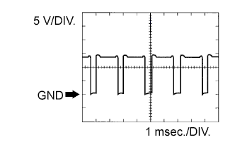 |
- Throttle actuator positive terminal
| Item | Content |
| Symbols (Terminal No.) | M+ (E15-5) - ME01 (E16-3) |
| Tool Setting | 5 V/DIV., 1 msec./DIV. |
| Condition | Idling with warm engine |
- HINT:
- The duty ratio varies depending on the throttle actuator operation.
| WAVEFORM 11 |
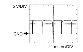 |
- Throttle actuator negative terminal
| Item | Content |
| Symbols (Terminal No.) | M- (E15-4) - ME01 (E16-3) |
| Tool Setting | 5 V/DIV., 1 msec./DIV. |
| Condition | Idling with warm engine |
- HINT:
- The duty ratio varies depending on the throttle actuator operation.
| WAVEFORM 12 |
 |
- Engine speed signal
| Item | Content |
| Symbols (Terminal No.) | TACH (E13-1) - E1 (E17-1) |
| Tool Setting | 5 V/DIV., 10 msec./DIV. |
| Condition | Idling |
- HINT:
- The wavelength becomes shorter as the engine rpm increases.