REMOVE COOLER COMPRESSOR V BELT (w/ Air Conditioning System)
DISCONNECT COMPRESSOR AND MAGNET CLUTCH (w/ Air Conditioning System)
REMOVE COMPRESSOR MOUNTING BRACKET (w/ Air Conditioning System)
Engine Assembly -- Removal |
| 1. DISCONNECT CABLE FROM NEGATIVE BATTERY TERMINAL |
- CAUTION:
- Wait at least 90 seconds after disconnecting the cable from the negative (-) battery terminal to prevent airbag activation.
| 2. REMOVE HOOD SUB-ASSEMBLY |
Disconnect the washer nozzle hose.
Remove the 4 bolts and hood.
| 3. REMOVE NO. 1 ENGINE UNDER COVER |
Remove the 8 bolts and under cover.
| 4. REMOVE NO. 2 ENGINE UNDER COVER |
Remove the 4 bolts and under cover.
| 5. LOOSEN FUEL TANK CAP ASSEMBLY |
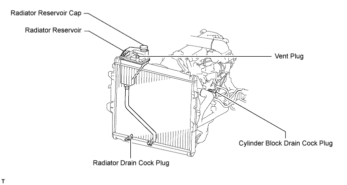
| 6. DRAIN ENGINE COOLANT |
- CAUTION:
- Do not remove the radiator reservoir cap while the engine and radiator are still hot. Pressurized, hot engine coolant and steam may be released and cause serious burns.
Remove the reservoir cap and, using a wrench, remove the vent plug.
 |
Loosen the cylinder block drain cock plug and the radiator drain cock plug.
- HINT:
- Collect the coolant in a container and dispose of it according to the regulations in your area.
| 7. DRAIN ENGINE OIL |
Remove the oil filler cap.
Remove the oil drain plug, and drain the oil into a container.
Clean the drain plug, and install it and a new gasket.
- Torque:
- 35 N*m{357 kgf*cm, 26 ft.*lbf}
| 8. REMOVE BATTERY BRACKET |
Remove the bolt and battery bracket.
| 9. REMOVE BATTERY AND BATTERY TRAY |
| 10. REMOVE AIR CLEANER ASSEMBLY |
Disconnect the IAT sensor connector.
Loosen the air cleaner hose clamp.
Remove the 2 bolts and air cleaner.
| 11. DISCONNECT RADIATOR HOSE INLET |
| 12. DISCONNECT RADIATOR HOSE OUTLET |
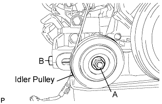
| 13. REMOVE VANE PUMP V BELT |
Loosen bolt A and nut B, and remove the V belt.
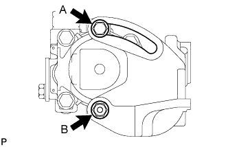 |
| 14. REMOVE COOLER COMPRESSOR V BELT (w/ Air Conditioning System) |
Loosen nut A and bolt B, and remove the V belt.
 |
| 15. REMOVE FAN & GENERATOR V BELT (w/o Air Conditioning System) |
Loosen the bolts A and B, and remove the V belt.
 |
| 16. REMOVE FAN & GENERATOR V BELT (w/ Air Conditioning System) |
Loosen the bolts A and B.
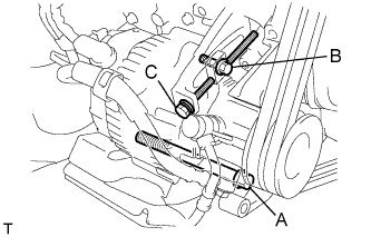 |
Loosen adjusting bolt C, and remove the V belt.
| 17. REMOVE FAN SHROUD |
Remove the 3 bolts and oil reservoir.
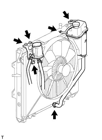 |
Disconnect the No. 1 and No. 2 water by-pass hoses from the tank upper and lower.
Remove the bolt and radiator reservoir.
Loosen the 4 nuts holding the fluid coupling fan.
Remove the vane pump V belt, cooler compressor V belt and fan and generator V belt (Toyota Fortuner RM00000122Y002X.html).
Remove the 2 bolts holding the fan shroud.
Remove the 4 nuts of the fluid coupling fan, and then remove the shroud together with the coupling fan.
- NOTICE:
- Be careful not to damage the radiator core.
Remove the fan pulley from the water pump.
| 18. REMOVE RADIATOR ASSEMBLY |
 |
Remove the 4 bolts and radiator.
| 19. REMOVE STARTER ASSEMBLY |
Disconnect the starter connector.
 |
Remove the terminal cap.
Remove the nut, and disconnect the terminal 30 wire.
Remove the nut, 2 bolts and stay.
 |
Remove the nut, 2 bolts and starter.
| 20. REMOVE NO. 1 EXHAUST MANIFOLD HEAT INSULATOR |
Remove the 3 bolts and heat insulator.
| 21. REMOVE FRONT EXHAUST PIPE ASSEMBLY |
Remove the 2 bolts from the transmission.
Remove the 5 clips and front fender seal LH.
Remove the 3 nuts from the exhaust manifold.
Disconnect the front exhaust pipe from the exhaust manifold and remove the gasket.
Remove the bolt, clamp and pipe support from the front exhaust pipe.
| 22. REMOVE PROPELLER SHAFT ASSEMBLY |
for Front Side:
Remove the propeller shaft (Toyota Fortuner RM0000010QG009X.html).
for Rear Side:
Remove the propeller shaft (Toyota Fortuner RM000000ZZ3008X.html).
| 23. REMOVE TRANSMISSION ASSEMBLY |
 |
Using a transmission jack, support the transmission.
Remove the support stand from the rear side.
Remove the 4 bolts and transmission.
| 24. REMOVE CLUTCH COVER ASSEMBLY |
 |
Place matchmarks on the clutch cover and flywheel.
Loosen each set bolt one turn at a time until spring tension is released.
Remove the 6 set bolts and pull off the clutch cover.
- NOTICE:
- Do not drop the clutch disc.
| 25. REMOVE CLUTCH DISC ASSEMBLY |
- NOTICE:
- Keep the lining part of the clutch disc, pressure plate and surface of the flywheel away from oil and foreign matter.
| 26. REMOVE FLYWHEEL SUB-ASSEMBLY |
 |
Using SST, hold the crankshaft.
- SST
- 09213-54015(91651-60855)
09330-00021
Remove the 8 bolts and flywheel.
| 27. REMOVE REAR END PLATE |
Remove the 2 bolts and rear end plate.
| 28. DISCONNECT HOSES AND CONNECTORS |
Remove the engine room relay block cover (upper).
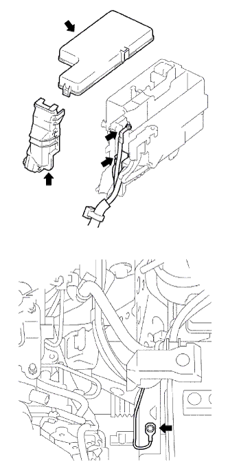 |
Remove the engine room relay block cover (side).
Remove the nut and disconnect the engine room junction block wire.
Disconnect the 2 engine room junction block connectors.
Remove the bolt and disconnect the ground cable.
Disconnect the 2 fuel hoses.
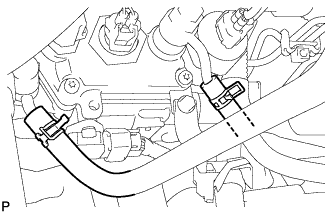 |
Disconnect the 2 water hoses.
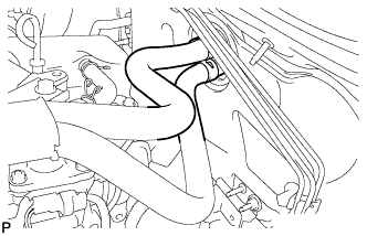 |
Remove the water hose clamp bolt.
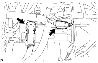
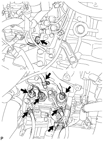
Disconnect the compressor connector.
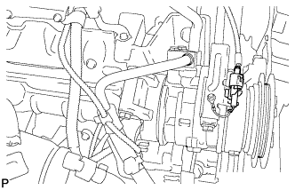 |
Disconnect the connectors as shown in the illustration.
 |
Disconnect the vacuum pump hose from the generator.
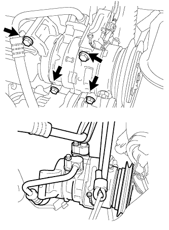
| 29. DISCONNECT COMPRESSOR AND MAGNET CLUTCH (w/ Air Conditioning System) |
Remove the 4 bolts and disconnect the cooler compressor.
- HINT:
- It is not necessary to completely remove the compressor. With the hoses connected to the compressor, hang the compressor on the vehicle body with a rope.
 |
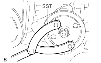
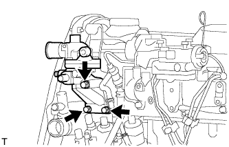
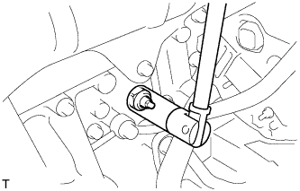
| 30. DISCONNECT VANE PUMP ASSEMBLY |
Using SST, stop the pulley rotation and loosen the nut.
- SST
- 09960-10010(09962-01000,09963-01000)
 |
Remove the nut and vane pump pulley from the vane pump shaft.
Remove the 2 bolts and nut, and disconnect the vane pump.
- HINT:
- Disconnect the vane pump with the hoses connected, and it should be hung with a rope.
| 31. INSTALL NO. 2 ENGINE HANGER |
Set the No. 2 engine hanger to the location shown in the illustration.
- Torque:
- 37 N*m{380 kgf*cm, 27 ft.*lbf}
Engine hanger part No.: Part Name Part No. No. 2 engine hanger 12282-54050 Bolt 91622-61022 - NOTICE:
- Install the engine hanger with new bolt.
 |
| 32. REMOVE ENGINE ASSEMBLY |
Hold the engine with an engine sling device and chain block.
Remove the 4 bolts and 4 nuts.
Remove the engine by operating the engine sling device and chain block.
| 33. INSTALL ENGINE ON ENGINE STAND |
| 34. REMOVE ENGINE WIRE |
Remove the engine wire from the engine assembly.
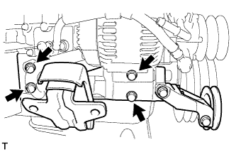
| 35. REMOVE FAN BELT ADJUSTING BAR (w/o Air Conditioning System) |
Remove the 3 bolts and fan belt adjusting bar.
 |
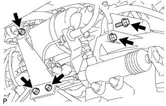
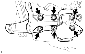
| 36. REMOVE COMPRESSOR MOUNTING BRACKET (w/ Air Conditioning System) |
Remove the bolt and spacer.
 |
Remove the 4 bolts and compressor mounting bracket.
 |
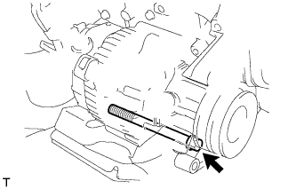
| 37. REMOVE GENERATOR ASSEMBLY |
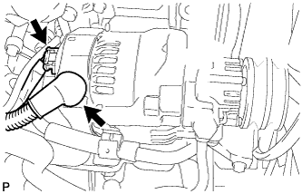 |
Detach the terminal cap.
Remove the nut and generator wire.
Disconnect the generator connector.
Remove the union bolt to disconnect the vacuum pump hose and remove the 2 gaskets.
 |
Remove the union bolt to disconnect the vacuum pump oil inlet hose and remove the 2 gaskets.
Detach the vacuum pump oil inlet hose from the cord clip.
Disconnect the vacuum pump oil outlet hose.
Remove the bolt and generator.
 |
| 38. REMOVE INTAKE PIPE |
Loosen the intake pipe clamp.
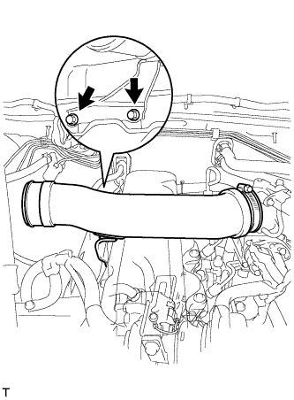 |
Remove the 2 bolts and intake pipe.
| 39. REMOVE OIL DIPSTICK SUB-ASSEMBLY |
| 40. REMOVE OIL DIPSTICK GUIDE |
Remove the 2 bolts, guide and O-ring.
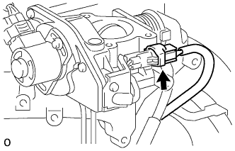
| 41. REMOVE VENTURI ASSEMBLY |
Disconnect the throttle open switch connector.
 |
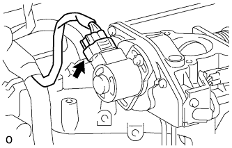
Disconnect the throttle control motor connector.
 |
Remove the venturi and gasket.
| 42. REMOVE INJECTION PIPE SET |
Using a union nut wrench, loosen the 8 union nuts of the 4 injection pipes.
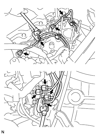 |
Remove the 2 nuts, 2 upper pipe clamps and 4 injection pipes together with the lower pipe clamps.
| 43. REMOVE NO. 1 GLOW PLUG CONNECTOR |
Remove the nut and disconnect the glow plug connector wire.
Remove the 4 screw grommets, 4 nuts and glow plug connector.
| 44. REMOVE NOZZLE LEAKAGE PIPE ASSEMBLY |
Disconnect the fuel hose from the leakage pipe.
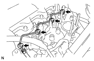 |
Remove the 4 nuts, leakage pipe and 4 ring packing washers.
| 45. REMOVE NOZZLE HOLDER & NOZZLE SET |
Using SST, remove the 4 injection nozzles, 4 injection nozzle seats and 4 injection nozzle seat gaskets.
- SST
- 09268-64010(09268-64020)
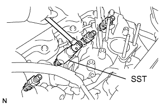 |
| 46. REMOVE GLOW PLUG ASSEMBLY |
Using a 12 mm deep socket wrench, remove the 4 glow plugs.
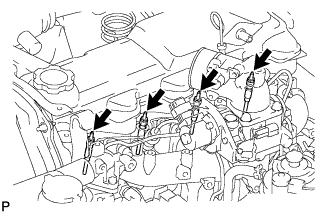 |
| 47. REMOVE INJECTION PUMP DRIVE PULLEY |
Using SST, remove the pulley nut.
- SST
- 09213-14010(91651-60865)
09330-00021
 |
Using SST, remove the drive pulley.
- SST
- 09950-50013(09951-05010,09952-05010,09953-05010,09954-05021)
 |
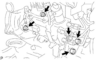
| 48. REMOVE INJECTION PUMP ASSEMBLY |
Disconnect the engine speed sensor connector.
 |
Disconnect the spill control valve connector.
Disconnect the correction unit connector.
Disconnect the timing control valve connector.
Disconnect the fuel temperature sensor connector.
Disconnect the engine wire clamp.
Disconnect the 3 fuel hoses.
Remove the 3 bolts and injection pump stay.
 |
Remove the 2 nuts and injection pump.
| 49. REMOVE CRANKSHAFT POSITION SENSOR |
Disconnect the sensor connector.
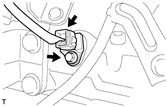 |
Remove the bolt and sensor.
| 50. REMOVE ENGINE COOLANT TEMPERATURE SENSOR |
Disconnect the sensor connector.
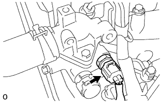 |
Remove the sensor and gasket.
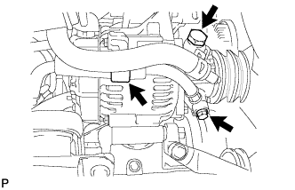
| 51. REMOVE WATER OUTLET HOUSING |
Remove the 3 bolts, outlet housing and gasket.
 |
| 52. REMOVE INTAKE MANIFOLD |
Remove the 6 bolts, 2 nuts, intake manifold and gasket.
 |
| 53. REMOVE WATER BY-PASS HOSE UNION |
Remove the water by-pass hose union.
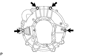
| 54. REMOVE PUMP BRACKET |
Remove the 6 bolts and pump bracket.
 |
| 55. REMOVE NO. 1 FRONT ENGINE MOUNTING BRACKET RH |
Remove the 4 bolts and engine mounting bracket.
 |
| 56. REMOVE EXHAUST MANIFOLD |
Remove the 6 bolts, 2 nuts and manifold.
 |
Remove the manifold gasket from the cylinder head.
| 57. REMOVE ENGINE OIL PRESSURE SWITCH ASSEMBLY |
Using a 24 mm deep socket wrench, remove the oil pressure switch.
 |
| 58. REMOVE WIRE HARNESS CLAMP BRACKET |
Remove the bolt and wire harness clamp bracket.