DTC P0351 Ignition Coil "A" Primary / Secondary Circuit
DTC P0352 Ignition Coil "B" Primary / Secondary Circuit
DTC P0353 Ignition Coil "C" Primary / Secondary Circuit
DTC P0354 Ignition Coil "D" Primary / Secondary Circuit
-
Check harness and connector (ignition coil assembly - body ground)
-
Check whether dtc output recurs (dtc p0351, p0352, p0353 or p0354)
Description
HINT:
- These DTCs indicate malfunctions relating to the primary circuit.
- If DTC P0351 is set, check the No. 1 ignition coil assembly circuit.
- If DTC P0352 is set, check the No. 2 ignition coil assembly circuit.
- If DTC P0353 is set, check the No. 3 ignition coil assembly circuit.
- If DTC P0354 is set, check the No. 4 ignition coil assembly circuit.
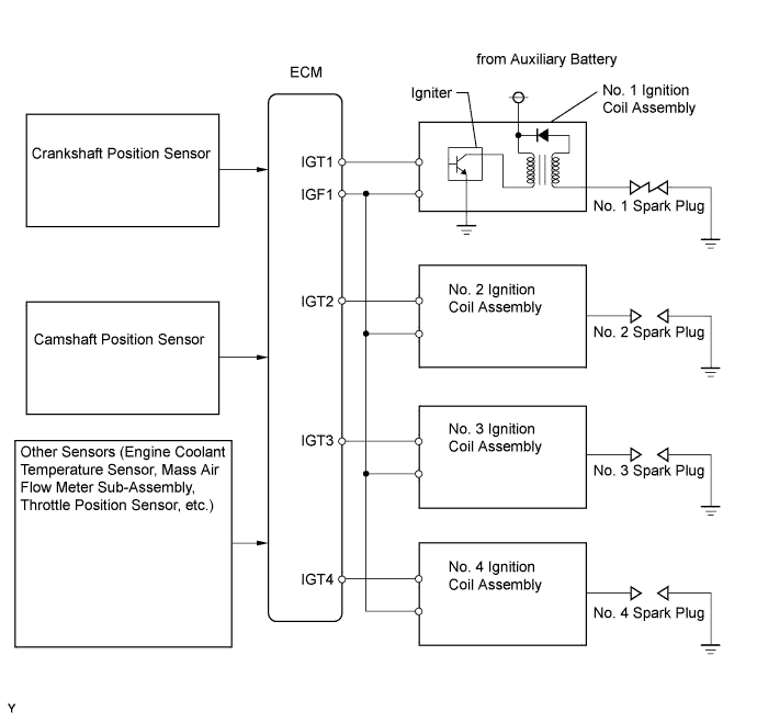
A Direct Ignition System (DIS) is used on this vehicle. The DIS is an ignition system in which each cylinder is ignited by it's own ignition coil assembly and spark plug. The secondary wiring of each ignition coil generates a powerful voltage which is applied directly to each spark plug. The spark passes from the center electrode of the spark plug to the ground electrode. The ECM determines the ignition timing and transmits the ignition (IGT) signals to each cylinder. Using the IGT signal, the ECM turns the power transistor inside the igniter on and off. The power transistor, in turn, switches on and off the current to the primary coil. When the current to the primary coil is cut off, a powerful voltage is generated in the secondary coil. This voltage is applied to the spark plugs, causing them to spark inside the cylinders. As the ECM cuts the current to the primary coil, the igniter sends back an ignition confirmation (IGF) signal to the ECM, for each cylinder ignition.
| DTC No. | DTC Detection Conditions | Trouble Areas |
| P0351 P0352 P0353 P0354 | No IGF signal to ECM while engine running (1 trip detection logic). |
|
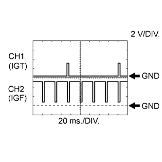 Reference: Inspection using an oscilloscope.
Standard:
Tester Connection Tool Setting Condition Specified Condition D27-108 (IGT1) - D27-104 (E1) 2 V/DIV., 20 ms./DIV. Idling The correct waveform is as shown D27-107 (IGT2) - D27-104 (E1) 2 V/DIV., 20 ms./DIV. Idling The correct waveform is as shown D27-106 (IGT3) - D27-104 (E1) 2 V/DIV., 20 ms./DIV. Idling The correct waveform is as shown D27-105 (IGT4) - D27-104 (E1) 2 V/DIV., 20 ms./DIV. Idling The correct waveform is as shown D27-23 (IGF1) - D27-104 (E1) 2 V/DIV., 20 ms./DIV. Idling The correct waveform is as shown - While cranking or idling the engine, check the waveform between terminals IGT (1 to 4) and E1, and IGF1 and E1 of the ECM connector.
Monitor description
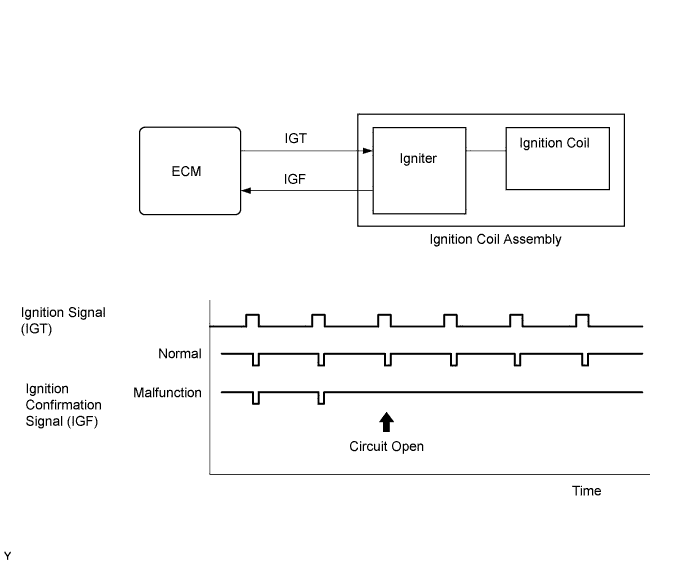
If the ECM does not receive any IGF signals despite transmitting the IGT signal, it interprets this as a fault in the igniter and sets a DTC.
Monitor strategy
| Required Sensors/Components (Main) | Igniter |
| Required Sensors/Components (Related) | Crankshaft position sensor |
| Frequency of Operation | Continuous |
Confirmation driving pattern
- Put the engine in inspection mode (maintenance mode) .
- Start the engine and run it at idle for 10 seconds or more.
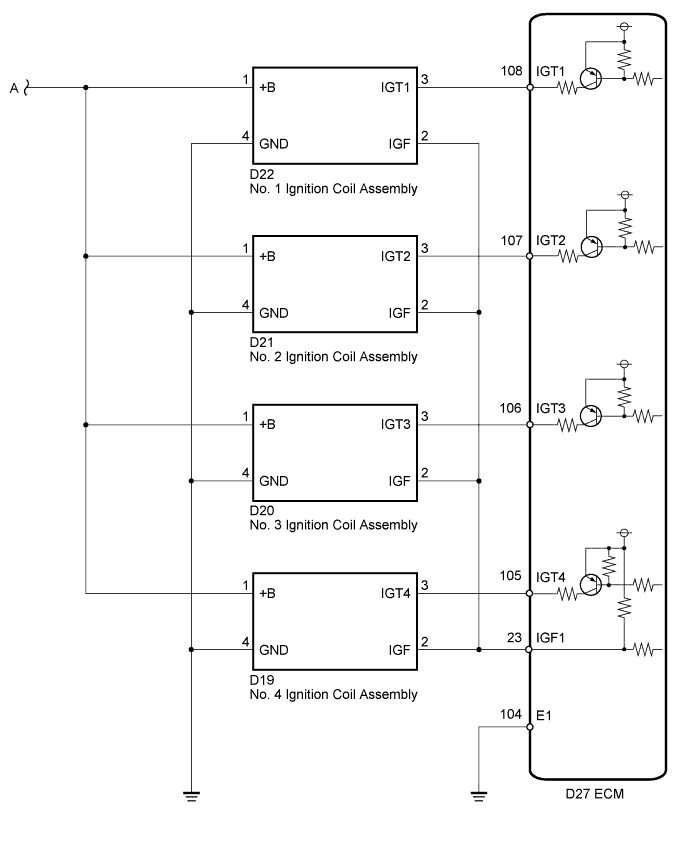
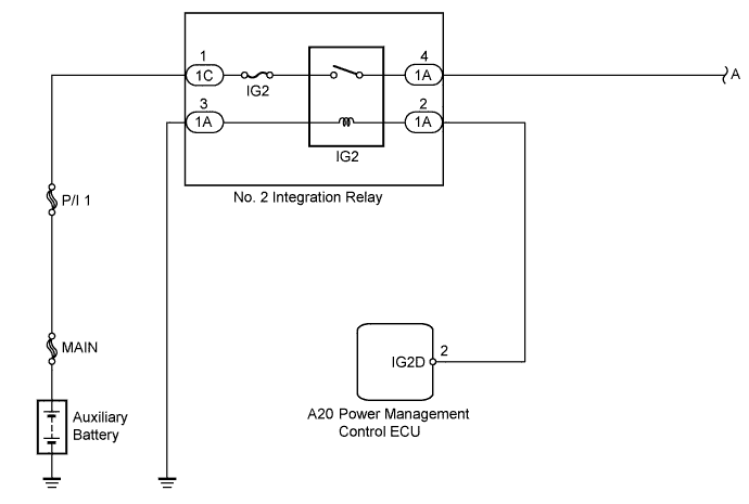
Wiring diagram
Inspection procedure
NOTICE:
Inspect the fuses for circuits related to this system before performing the following inspection procedure.
HINT:
Read freeze frame data using the intelligent tester. The ECM records vehicle and driving condition information as freeze frame data the moment a DTC is stored. When troubleshooting, freeze frame data can be helpful in determining whether the vehicle was running or stopped, whether the engine was warmed up or not, whether the air fuel ratio was lean or rich, as well as other data recorded at the time of a malfunction.
| 1.CHECK HARNESS AND CONNECTOR (IGNITION COIL ASSEMBLY - BODY GROUND) |
-
Disconnect the ignition coil assembly connectors.
-
Measure the resistance according to the value(s) in the table below.
Standard Resistance:
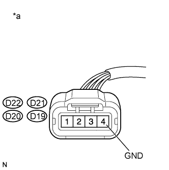
Tester Connection Condition Specified Condition D22-4 (GND) - Body ground Always Below 1 ? D21-4 (GND) - Body ground Always Below 1 ? D20-4 (GND) - Body ground Always Below 1 ? D19-4 (GND) - Body ground Always Below 1 ? Text in Illustration *a Front view of wire harness connector (to Ignition Coil Assembly)
|
|
||||
| OK | |
| 2.INSPECT IGNITION COIL ASSEMBLY (POWER SOURCE) |
-
Disconnect the ignition coil assembly connectors.
-
Turn the power switch on (IG).
-
Measure the voltage according to the value(s) in the table below.
Standard Voltage:
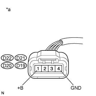
Tester Connection Switch Condition Specified Condition D22-1 (+B) - D22-4 (GND) Power switch on (IG) 11 to 14 V D21-1 (+B) - D21-4 (GND) Power switch on (IG) 11 to 14 V D20-1 (+B) - D20-4 (GND) Power switch on (IG) 11 to 14 V D19-1 (+B) - D19-4 (GND) Power switch on (IG) 11 to 14 V Text in Illustration *a Front view of wire harness connector (to Ignition Coil Assembly)
|
|
||||
| OK | |
| 3.CHECK HARNESS AND CONNECTOR (IGNITION COIL ASSEMBLY - ECM) |
-
Disconnect the ignition coil assembly connectors.
-
Disconnect the ECM connector.
-
Measure the resistance according to the value(s) in the table below.
Standard Resistance:
Tester Connection Condition Specified Condition D22-2 (IGF) - D27-23 (IGF1) Always Below 1 ? D21-2 (IGF) - D27-23 (IGF1) Always Below 1 ? D20-2 (IGF) - D27-23 (IGF1) Always Below 1 ? D19-2 (IGF) - D27-23 (IGF1) Always Below 1 ? D22-3 (IGT1) - D27-108 (IGT1) Always Below 1 ? D21-3 (IGT2) - D27-107 (IGT2) Always Below 1 ? D20-3 (IGT3) - D27-106 (IGT3) Always Below 1 ? D19-3 (IGT4) - D27-105 (IGT4) Always Below 1 ? D22-2 (IGF) or D27-23 (IGF1) - Body ground Always 10 k? or higher D21-2 (IGF) or D27-23 (IGF1) - Body ground Always 10 k? or higher D20-2 (IGF) or D27-23 (IGF1) - Body ground Always 10 k? or higher D19-2 (IGF) or D27-23 (IGF1) - Body ground Always 10 k? or higher D22-3 (IGT1) or D27-108 (IGT1) - Body ground Always 10 k? or higher D21-3 (IGT2) or D27-107 (IGT2) - Body ground Always 10 k? or higher D20-3 (IGT3) or D27-106 (IGT3) - Body ground Always 10 k? or higher D19-3 (IGT4) or D27-105 (IGT4) - Body ground Always 10 k? or higher
|
|
||||
| OK | |
| 4.CHECK WHETHER DTC OUTPUT RECURS (DTC P0351, P0352, P0353 OR P0354) |
-
Connect the intelligent tester to the DLC3.
-
Turn the power switch on (IG).
-
Turn the tester on.
-
Clear the DTCs .
-
Shuffle arrangement of the ignition coil assemblies (among No. 1 to No. 4 cylinders).
NOTICE:
Do not shuffle the connectors.
-
Drive the vehicle in accordance with the driving pattern described in the Confirmation Driving Pattern.
-
Enter the following menus: Powertrain / Engine and ECT / DTC.
-
Read the DTCs.
Result Result Proceed to Same DTC output A Different ignition coil DTC output B
|
|
||||
| A | |
|