DESCRIPTION
WIRING DIAGRAM
INSPECTION PROCEDURE
READ VALUE USING TECHSTREAM
INSPECT FRONT DOOR COURTESY LIGHT SWITCH ASSEMBLY LH
CHECK HARNESS AND CONNECTOR (FRONT DOOR COURTESY LIGHT SWITCH ASSEMBLY LH - INSTRUMENT PANEL JUNCTION BLOCK ASSEMBLY)
INSPECT INSTRUMENT PANEL JUNCTION BLOCK ASSEMBLY
INSPECT FRONT DOOR COURTESY LIGHT SWITCH ASSEMBLY RH
CHECK HARNESS AND CONNECTOR (FRONT DOOR COURTESY LIGHT SWITCH ASSEMBLY RH - MAIN BODY ECU)
INSPECT REAR DOOR COURTESY LIGHT SWITCH ASSEMBLY
CHECK HARNESS AND CONNECTOR (REAR DOOR COURTESY LIGHT SWITCH ASSEMBLY - MAIN BODY ECU)
INSPECT BACK DOOR LOCK ASSEMBLY (BACK DOOR COURTESY SWITCH)
CHECK HARNESS AND CONNECTOR (BACK DOOR LOCK ASSEMBLY - INSTRUMENT PANEL JUNCTION BLOCK ASSEMBLY AND BODY GROUND)
INSPECT INSTRUMENT PANEL JUNCTION BLOCK ASSEMBLY
CHECK HARNESS AND CONNECTOR (BACK DOOR LOCK ASSEMBLY - MAIN BODY ECU AND BODY GROUND)
LIGHTING SYSTEM (for Hatchback) - Door Courtesy Switch Circuit |
DESCRIPTION
The main body ECU detects the condition of each door courtesy light switch.
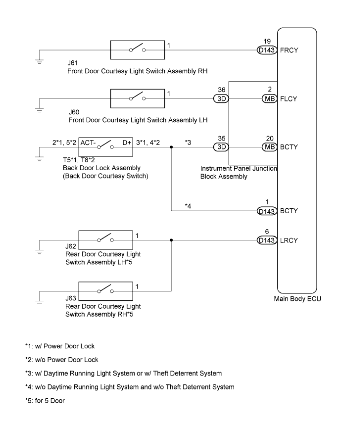
WIRING DIAGRAM
INSPECTION PROCEDURE
| 1.READ VALUE USING TECHSTREAM |
Connect the Techstream to the DLC3.
Turn the ignition switch to ON.
Turn the Techstream on.
Enter the following menus: Body Electrical / Main Body / Data List.
According to the display on the Techstream, read the Data List.
Main BodyTester Display
| Measurement Item/Range
| Normal Condition
| Diagnostic Note
|
RR Door Courtesy SW*1
| Rear door courtesy light switch LH and RH signal /
OFF or ON
| OFF: Rear door LH and RH closed
ON: Rear door LH or RH opened
| -
|
RL Door Courtesy SW*1
| Rear door courtesy light switch LH and RH signal /
OFF or ON
| OFF: Rear door LH and RH closed
ON: Rear door LH or RH opened
| -
|
Back Door Courtesy SW
| Back door courtesy light switch signal /
OFF or ON
| OFF: Back door closed
ON: Back door opened
| -
|
FR Door Courtesy
| Front door courtesy light switch RH signal /
ON or OFF
| ON: Front door RH closed
OFF: Front door RH opened
| -
|
FL Door Courtesy
| Front door courtesy light switch LH signal /
ON or OFF
| ON: Front door LH closed
OFF: Front door LH opened
| -
|
- *1: for 5 Door
- OK:
- Normal conditions listed above are displayed.
ResultResult
| Proceed to
|
OK
| A
|
NG (Front door courtesy light switch assembly LH does not operate)
| B
|
NG (Front door courtesy light switch assembly RH does not operate)
| C
|
NG (Rear door courtesy light switch assembly does not operate)*1
| D
|
NG (Back door courtesy switch)
| E
|
- *1: for 5 Door
| 2.INSPECT FRONT DOOR COURTESY LIGHT SWITCH ASSEMBLY LH |
Inspect the front door courtesy light switch assembly LH (YARIS_NCP93 RM000001Y5501GX.html).
| 3.CHECK HARNESS AND CONNECTOR (FRONT DOOR COURTESY LIGHT SWITCH ASSEMBLY LH - INSTRUMENT PANEL JUNCTION BLOCK ASSEMBLY) |
Disconnect the J60 front door courtesy light switch assembly LH connector.
Disconnect the 3D instrument panel junction block assembly connector.
Measure the resistance according to the value(s) in the table below.
- Standard Resistance:
Tester Connection
| Condition
| Specified Condition
|
J60-1 - 3D-36
| Always
| Below 1 Ω
|
J60-1 - Body ground
| Always
| 10 kΩ or higher
|
| | REPAIR OR REPLACE HARNESS OR CONNECTOR |
|
|
| 4.INSPECT INSTRUMENT PANEL JUNCTION BLOCK ASSEMBLY |
Remove the instrument panel junction block assembly.
Remove the main body ECU from the instrument panel junction block assembly.
Measure the resistance according to the value(s) in the table below.
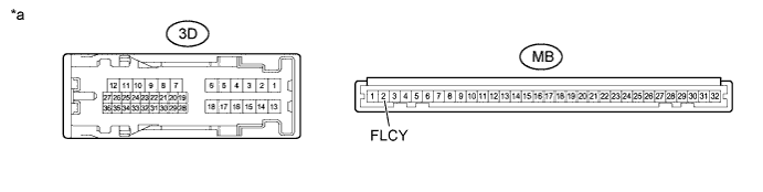
Text in Illustration*a
| Component without harness connected
(Instrument Panel Junction Block Assembly)
| -
| -
|
- Standard Resistance:
Tester Connection
| Condition
| Specified Condition
|
3D-36 - MB-2 (FLCY)
| Always
| Below 1 Ω
|
| | REPLACE INSTRUMENT PANEL JUNCTION BLOCK ASSEMBLY |
|
|
| 5.INSPECT FRONT DOOR COURTESY LIGHT SWITCH ASSEMBLY RH |
Inspect the front door courtesy light switch assembly RH (YARIS_NCP93 RM000001Y5501GX.html).
| 6.CHECK HARNESS AND CONNECTOR (FRONT DOOR COURTESY LIGHT SWITCH ASSEMBLY RH - MAIN BODY ECU) |
Disconnect J61 front door courtesy light switch assembly RH connector.
Disconnect the D143 main body ECU connector.
Measure the resistance according to the value(s) in the table below.
- Standard Resistance:
Tester Connection
| Condition
| Specified Condition
|
J61-1 - D143-19 (FRCY)
| Always
| Below 1 Ω
|
J61-1 - Body ground
| Always
| 10 kΩ or higher
|
| | REPAIR OR REPLACE HARNESS OR CONNECTOR |
|
|
| 7.INSPECT REAR DOOR COURTESY LIGHT SWITCH ASSEMBLY |
Inspect the rear door courtesy light switch assembly (YARIS_NCP93 RM000001Y5601AX.html).
| 8.CHECK HARNESS AND CONNECTOR (REAR DOOR COURTESY LIGHT SWITCH ASSEMBLY - MAIN BODY ECU) |
Disconnect J62 or J63 rear door courtesy light switch assembly connector.
Disconnect the D143 main body ECU connector.
Measure the resistance according to the value(s) in the table below.
- Standard Resistance:
LHTester Connection
| Condition
| Specified Condition
|
J62-1 - D143-6 (LRCY)
| Always
| Below 1 Ω
|
J62-1 - Body ground
| Always
| 10 kΩ or higher
|
RHTester Connection
| Condition
| Specified Condition
|
J63-1 - D143-6 (LRCY)
| Always
| Below 1 Ω
|
J63-1 - Body ground
| Always
| 10 kΩ or higher
|
| | REPAIR OR REPLACE HARNESS OR CONNECTOR |
|
|
| 9.INSPECT BACK DOOR LOCK ASSEMBLY (BACK DOOR COURTESY SWITCH) |
Inspect the back door lock assembly (back door courtesy switch) (YARIS_NCP93 RM0000025EO00VX.html).
ResultResult
| Proceed to
|
NG
| A
|
OK (w/ Daytime Running Light System or w/ Theft Deterrent System)
| B
|
OK (w/o Daytime Running Light System and w/o Theft Deterrent System)
| C
|
| 10.CHECK HARNESS AND CONNECTOR (BACK DOOR LOCK ASSEMBLY - INSTRUMENT PANEL JUNCTION BLOCK ASSEMBLY AND BODY GROUND) |
w/ Power Door Lock
Disconnect the T5 back door lock assembly (back door courtesy switch) connector.
w/o Power Door Lock
Disconnect the T8 back door lock assembly (back door courtesy switch) connector.
Disconnect the 3D instrument panel junction block assembly connector.
Measure the resistance according to the value(s) in the table below.
- Standard Resistance:
w/ Power Door LockTester Connection
| Condition
| Specified Condition
|
T5-3 (D+) - 3D-35
| Always
| Below 1 Ω
|
T5-3 (D+) - Body ground
| Always
| 10 kΩ or higher
|
T5-2 (ACT-) - Body ground
| Always
| Below 1 Ω
|
w/o Power Door LockTester Connection
| Condition
| Specified Condition
|
T8-4 (D+) - 3D-35
| Always
| Below 1 Ω
|
T8-4 (D+) - Body ground
| Always
| 10 kΩ or higher
|
T8-5 (ACT-) - Body ground
| Always
| Below 1 Ω
|
| | REPAIR OR REPLACE HARNESS OR CONNECTOR |
|
|
| 11.INSPECT INSTRUMENT PANEL JUNCTION BLOCK ASSEMBLY |
Remove the instrument panel junction block assembly.
Remove the main body ECU from the instrument panel junction block assembly.
Measure the resistance according to the value(s) in the table below.
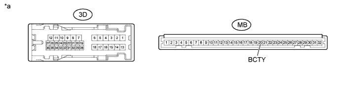
Text in Illustration*a
| Component without harness connected
(Instrument Panel Junction Block Assembly)
| -
| -
|
- Standard Resistance:
Tester Connection
| Condition
| Specified Condition
|
3D-35 - MB-20 (BCTY)
| Always
| Below 1 Ω
|
| | REPLACE INSTRUMENT PANEL JUNCTION BLOCK ASSEMBLY |
|
|
| 12.CHECK HARNESS AND CONNECTOR (BACK DOOR LOCK ASSEMBLY - MAIN BODY ECU AND BODY GROUND) |
w/ Power Door Lock
Disconnect the T5 back door lock assembly (back door courtesy switch) connector.
w/o Power Door Lock
Disconnect the T8 back door lock assembly (back door courtesy switch) connector.
Disconnect the D143 main body ECU connector.
Measure the resistance according to the value(s) in the table below.
- Standard Resistance:
w/ Power Door LockTester Connection
| Condition
| Specified Condition
|
T5-3 (D+) - D143-1 (BCTY)
| Always
| Below 1 Ω
|
T5-3 (D+) - Body ground
| Always
| 10 kΩ or higher
|
T5-2 (ACT-) - Body ground
| Always
| Below 1 Ω
|
w/o Power Door LockTester Connection
| Condition
| Specified Condition
|
T8-4 (D+) - D143-1 (BCTY)
| Always
| Below 1 Ω
|
T8-4 (D+) - Body ground
| Always
| 10 kΩ or higher
|
T8-5 (ACT-) - Body ground
| Always
| Below 1 Ω
|
| | REPAIR OR REPLACE HARNESS OR CONNECTOR |
|
|