Air Conditioning System (For Hatchback) Headlight Signal Circuit
DESCRIPTION
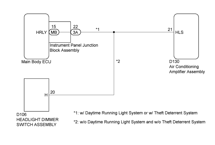
WIRING DIAGRAM
INSPECTION PROCEDURE
INSPECT HEADLIGHT ASSEMBLY
CHECK HARNESS AND CONNECTOR (INSTRUMENT PANEL JUNCTION BLOCK ASSEMBLY - AIR CONDITIONING AMPLIFIER ASSEMBLY)
INSPECT INSTRUMENT PANEL JUNCTION BLOCK ASSEMBLY
CHECK HARNESS AND CONNECTOR (HEADLIGHT DIMMER SWITCH ASSEMBLY - AIR CONDITIONING AMPLIFIER ASSEMBLY)
AIR CONDITIONING SYSTEM (for Hatchback) - Headlight Signal Circuit |
DESCRIPTION
The air conditioning amplifier assembly receives headlight operational signals to determine electrical load conditions. The electrical load condition signals are used for controlling the number of the PTC heater elements to be heated.
WIRING DIAGRAM
INSPECTION PROCEDURE
| 1.INSPECT HEADLIGHT ASSEMBLY |
Check that the headlight comes on when the light control switch is turned to the HEAD position.
- OK:
- The headlight comes on.
ResultResult
| Proceed to
|
NG
| A
|
OK (w/ Daytime Running Light System or w/ Theft Deterrent System)
| B
|
OK (w/o Daytime Running Light System and w/o Theft Deterrent System)
| C
|
| 2.CHECK HARNESS AND CONNECTOR (INSTRUMENT PANEL JUNCTION BLOCK ASSEMBLY - AIR CONDITIONING AMPLIFIER ASSEMBLY) |
Disconnect the 3A instrument panel junction block assembly connector.
Disconnect the D130 air conditioning amplifier assembly connector.
Measure the resistance according to the value(s) in the table below.
- Standard Resistance:
Tester Connection
| Condition
| Specified Condition
|
3A-22 - D130-21 (HLS)
| Always
| Below 1 Ω
|
3A-22 - Body ground
| Always
| 10 kΩ or higher
|
| | REPAIR OR REPLACE HARNESS OR CONNECTOR |
|
|
| 3.INSPECT INSTRUMENT PANEL JUNCTION BLOCK ASSEMBLY |
Remove the instrument panel junction block assembly.
Remove the main body ECU from the instrument panel junction block assembly.
Measure the resistance according to the value(s) in the table below.
Text in Illustration*a
| Component without harness connected
(Instrument Panel Junction Block Assembly)
| -
| -
|
- Standard Resistance:
Tester Connection
| Condition
| Specified Condition
|
3A-22 - MB-15 (HRLY)
| Always
| Below 1 Ω
|
| | REPLACE INSTRUMENT PANEL JUNCTION BLOCK ASSEMBLY |
|
|
| 4.CHECK HARNESS AND CONNECTOR (HEADLIGHT DIMMER SWITCH ASSEMBLY - AIR CONDITIONING AMPLIFIER ASSEMBLY) |
Disconnect the D106 headlight dimmer switch assembly connector.
Disconnect the D130 air conditioning amplifier assembly connector.
Measure the resistance according to the value(s) in the table below.
- Standard Resistance:
Tester Connection
| Condition
| Specified Condition
|
D106-20 (H) - D130-21 (HLS)
| Always
| Below 1 Ω
|
D106-20 (H) - Body ground
| Always
| 10 kΩ or higher
|
| | REPAIR OR REPLACE HARNESS OR CONNECTOR |
|
|