DESCRIPTION
WIRING DIAGRAM
INSPECTION PROCEDURE
INSPECT HEATER BLOWER MOTOR RELAY ASSEMBLY (HTR RELAY)
INSPECT BLOWER MOTOR WITH FAN SUB-ASSEMBLY
CHECK HARNESS AND CONNECTOR (HEATER BLOWER MOTOR RELAY ASSEMBLY (HTR RELAY) - BATTERY, IG1 NO. 1 RELAY AND BODY GROUND)
CHECK HARNESS AND CONNECTOR (HEATER BLOWER MOTOR RELAY ASSEMBLY (HTR RELAY) - AIR CONDITIONING AMPLIFIER ASSEMBLY)
CHECK HARNESS AND CONNECTOR (NO. 2 HEATER CONTROL SUB-ASSEMBLY - AIR CONDITIONING AMPLIFIER ASSEMBLY)
CHECK HARNESS AND CONNECTOR (BLOWER MOTOR WITH FAN SUB-ASSEMBLY - HEATER BLOWER MOTOR RELAY ASSEMBLY (HTR RELAY))
CHECK HARNESS AND CONNECTOR (BLOWER MOTOR WITH FAN SUB-ASSEMBLY - BLOWER RESISTOR)
INSPECT BLOWER RESISTOR
INSPECT NO. 2 HEATER CONTROL SUB-ASSEMBLY (BLOWER SWITCH)
CHECK HARNESS AND CONNECTOR (NO. 2 HEATER CONTROL SUB-ASSEMBLY - BLOWER RESISTOR AND BODY GROUND)
AIR CONDITIONING SYSTEM (for Hatchback) - Blower Motor Circuit |
DESCRIPTION
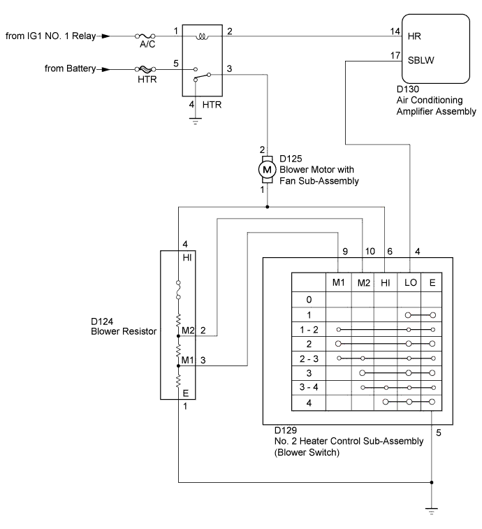
When the No. 2 heater control sub-assembly (blower switch) is set to position 1 or higher, the contact of the heater blower motor relay assembly (HTR relay) relay is closed, current flows to the blower motor, and the blower motor operates. The blower motor speed can be changed by exchanging the ground and the blower resistor circuit with the No. 2 heater control sub-assembly (blower switch).
WIRING DIAGRAM
INSPECTION PROCEDURE
- NOTICE:
- Inspect the fuses for circuits related to this system before performing the following inspection procedure.
| 1.INSPECT HEATER BLOWER MOTOR RELAY ASSEMBLY (HTR RELAY) |
Inspect the heater blower motor relay assembly (HTR relay) (YARIS_NCP93 RM000003WXB00BX.html).
| | REPLACE HEATER BLOWER MOTOR RELAY ASSEMBLY (HTR RELAY) |
|
|
| 2.INSPECT BLOWER MOTOR WITH FAN SUB-ASSEMBLY |
Inspect the blower motor with fan sub-assembly (YARIS_NCP93 RM00000314T01WX.html).
| 3.CHECK HARNESS AND CONNECTOR (HEATER BLOWER MOTOR RELAY ASSEMBLY (HTR RELAY) - BATTERY, IG1 NO. 1 RELAY AND BODY GROUND) |
Remove the heater blower motor relay assembly (HTR relay).
Measure the voltage according to the value(s) in the table below.
- Standard Voltage:
Tester Connection
| Switch Condition
| Specified Condition
|
HTR-5 - Body ground
| Always
| 11 to 14 V
|
HTR-1 - Body ground
| Ignition switch ON
| 11 to 14 V
|
Measure the resistance according to the value(s) in the table below.
- Standard Resistance:
Tester Connection
| Condition
| Specified Condition
|
HTR-4 - Body ground
| Always
| Below 1 Ω
|
Text in Illustration*1
| Heater Blower Motor Relay Assembly (HTR Relay) Holder
|
| | REPAIR OR REPLACE HARNESS OR CONNECTOR |
|
|
| 4.CHECK HARNESS AND CONNECTOR (HEATER BLOWER MOTOR RELAY ASSEMBLY (HTR RELAY) - AIR CONDITIONING AMPLIFIER ASSEMBLY) |
Remove the heater blower motor relay assembly (HTR relay).
Disconnect the D130 air conditioning amplifier assembly connector.
Measure the resistance according to the value(s) in the table below.
- Standard Resistance:
Tester Connection
| Condition
| Specified Condition
|
HTR-2 - D130-14 (HR)
| Always
| Below 1 Ω
|
HTR-2 - Body ground
| Always
| 10 kΩ or higher
|
| | REPAIR OR REPLACE HARNESS OR CONNECTOR |
|
|
| 5.CHECK HARNESS AND CONNECTOR (NO. 2 HEATER CONTROL SUB-ASSEMBLY - AIR CONDITIONING AMPLIFIER ASSEMBLY) |
Disconnect the D129 No. 2 heater control sub-assembly (blower switch) connector.
Disconnect the D130 air conditioning amplifier assembly connector.
Measure the resistance according to the value(s) in the table below.
- Standard Resistance:
Tester Connection
| Condition
| Specified Condition
|
D129-4 (LO) - D130-17 (SBLW)
| Always
| Below 1 Ω
|
D129-4 (LO) - Body ground
| Always
| 10 kΩ or higher
|
| | REPAIR OR REPLACE HARNESS OR CONNECTOR |
|
|
| 6.CHECK HARNESS AND CONNECTOR (BLOWER MOTOR WITH FAN SUB-ASSEMBLY - HEATER BLOWER MOTOR RELAY ASSEMBLY (HTR RELAY)) |
Disconnect the D125 blower motor with fan sub-assembly connector.
Measure the voltage according to the value(s) in the table below.
- Standard Voltage:
Tester Connection
| Switch Condition
| Specified Condition
|
D125-2 - Body ground
| Ignition switch ON
Blower switch ON
| 11 to 14 V
|
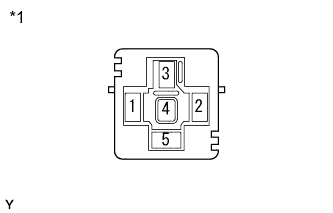
Text in Illustration*a
| Front view of wire harness connector
(to Blower Motor with Fan Sub-Assembly)
|
| | REPAIR OR REPLACE HARNESS OR CONNECTOR |
|
|
| 7.CHECK HARNESS AND CONNECTOR (BLOWER MOTOR WITH FAN SUB-ASSEMBLY - BLOWER RESISTOR) |
Disconnect the D125 blower motor with fan sub-assembly connector.
Disconnect the D124 blower resistor connector.
Measure the resistance according to the value(s) in the table below.
- Standard Resistance:
Tester Connection
| Condition
| Specified Condition
|
D125-1 - D124-4 (HI)
| Always
| Below 1 Ω
|
D125-1 - Body ground
| Always
| 10 kΩ or higher
|
| | REPAIR OR REPLACE HARNESS OR CONNECTOR |
|
|
| 8.INSPECT BLOWER RESISTOR |
Inspect the blower resistor (YARIS_NCP93 RM00000314S01RX.html).
| 9.INSPECT NO. 2 HEATER CONTROL SUB-ASSEMBLY (BLOWER SWITCH) |
Inspect the No. 2 heater control sub-assembly (blower switch) (YARIS_NCP93 RM00000314R026X.html).
| 10.CHECK HARNESS AND CONNECTOR (NO. 2 HEATER CONTROL SUB-ASSEMBLY - BLOWER RESISTOR AND BODY GROUND) |
Disconnect the D129 No. 2 heater control sub-assembly (blower switch) connector.
Disconnect the D124 blower resistor connector.
Measure the resistance according to the value(s) in the table below.
- Standard Resistance:
Tester Connection
| Condition
| Specified Condition
|
D129-5 (E) - D124-1 (E)
| Always
| Below 1 Ω
|
D129-10 (M2) - D124-2 (M2)
| Always
| Below 1 Ω
|
D129-9 (M1) - D124-3 (M1)
| Always
| Below 1 Ω
|
D129-6 (HI) - D124-4 (HI)
| Always
| Below 1 Ω
|
D129-5 (E) - Body ground
| Always
| Below 1 Ω
|
D129-10 (M2) - Body ground
| Always
| 10 kΩ or higher
|
D129-9 (M1) - Body ground
| Always
| 10 kΩ or higher
|
D129-6 (HI) - Body ground
| Always
| 10 kΩ or higher
|
| | REPAIR OR REPLACE HARNESS OR CONNECTOR |
|
|