Theft Deterrent System (For Hatchback) Ignition Switch Circuit
DESCRIPTION
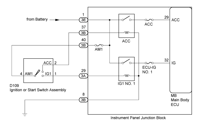
WIRING DIAGRAM
INSPECTION PROCEDURE
READ VALUE USING TECHSTREAM
CHECK HARNESS AND CONNECTOR (BATTERY - INSTRUMENT PANEL JUNCTION BLOCK)
INSPECT IGNITION OR START SWITCH ASSEMBLY
CHECK HARNESS AND CONNECTOR (IGNITION OR START SWITCH ASSEMBLY - INSTRUMENT PANEL JUNCTION BLOCK)
THEFT DETERRENT SYSTEM (for Hatchback) - Ignition Switch Circuit |
DESCRIPTION
The main body ECU determines the ignition switch position (OFF, ACC, ON) based on signals from the IG or ACC circuit.
WIRING DIAGRAM
INSPECTION PROCEDURE
- NOTICE:
- Inspect the fuses for circuits related to this system before performing the following inspection procedure.
| 1.READ VALUE USING TECHSTREAM |
Connect the Techstream to the DLC3.
Turn the ignition switch to ON.
Turn the Techstream on.
Enter the following menus: Body Electrical / Main Body / Data List.
According to the display on the Techstream, read the Data List.
Main BodyTester Display
| Measurement Item/Range
| Normal Condition
| Diagnostic Note
|
ACC SW
| Ignition switch / OFF or ON
| OFF: Ignition switch LOCK or ON
ON: Ignition switch ACC
| -
|
IG SW
| Ignition switch / OFF or ON
| OFF: Ignition switch LOCK or ACC
ON: Ignition switch ON
| -
|
- OK:
- When the ignition switch is operated, the display changes as shown in the table.
| 2.CHECK HARNESS AND CONNECTOR (BATTERY - INSTRUMENT PANEL JUNCTION BLOCK) |
Disconnect the 3E junction block connector.
Measure the voltage according to the value(s) in the table below.
- Standard Voltage:
Tester Connection
| Switch Condition
| Specified Condition
|
3E-1 - Body ground
| Ignition switch ON
| 11 to 14 V
|
Text in Illustration*a
| Front view of wire harness connector
(to Instrument Panel Junction Block)
|
| | REPAIR OR REPLACE HARNESS OR CONNECTOR |
|
|
| 3.INSPECT IGNITION OR START SWITCH ASSEMBLY |
Inspect the ignition or start switch assembly (YARIS_NCP93 RM000000X2S02EX.html).
| 4.CHECK HARNESS AND CONNECTOR (IGNITION OR START SWITCH ASSEMBLY - INSTRUMENT PANEL JUNCTION BLOCK) |
Reinstall the ignition or start switch assembly.
Disconnect the 3A and 3B junction block connector.
Measure the resistance according to the value(s) in the table below.
- Standard Resistance:
Tester Connection
| Switch Condition
| Specified Condition
|
3A-29 - 3B-40
| Ignition switch ON
| Below 1 Ω
|
3B-37 - 3D-40
| Ignition switch ACC
| Below 1 Ω
|
3D-8 - Body Ground
| Always
| Below 1 Ω
|
| | REPAIR OR REPLACE HARNESS OR CONNECTOR |
|
|