Air Conditioning Unit (For Hatchback) Removal
PRECAUTION
RECOVER REFRIGERANT FROM REFRIGERATION SYSTEM
DRAIN ENGINE COOLANT (for 1NZ-FE)
DISCONNECT CABLE FROM NEGATIVE BATTERY TERMINAL
REMOVE WINDSHIELD WIPER MOTOR AND LINK
REMOVE FRONT NO. 1 VENTILATOR SEAL
REMOVE FRONT AIR SHUTTER SEAL RH
REMOVE COWL TOP TO COWL INNER BRACE
REMOVE COWL TOP OUTER PANEL
DISCONNECT AIR CONDITIONER TUBE AND ACCESSORY ASSEMBLY
DISCONNECT HEATER WATER OUTLET HOSE A
DISCONNECT HEATER WATER INLET HOSE A
REMOVE LOWER INSTRUMENT PANEL SUB-ASSEMBLY
REMOVE STEERING COLUMN ASSEMBLY
REMOVE HEATER TO REGISTER DUCT ASSEMBLY
REMOVE DEFROSTER NOZZLE ASSEMBLY
REMOVE REAR NO. 2 AIR DUCT (for Cold Area Specification Vehicles)
REMOVE REAR NO. 4 AIR DUCT (for Cold Area Specification Vehicles)
REMOVE REAR NO. 3 AIR DUCT (for Cold Area Specification Vehicles)
SEPARATE DRAIN COOLER HOSE
REMOVE NO. 1 INSTRUMENT PANEL BRACE SUB-ASSEMBLY (except Cold Area Specification Vehicles)
REMOVE NO. 1 INSTRUMENT PANEL BRACE SUB-ASSEMBLY (for Cold Area Specification Vehicles)
REMOVE REAR NO. 1 AIR DUCT (for Cold Area Specification Vehicles)
REMOVE INSTRUMENT PANEL JUNCTION BLOCK ASSEMBLY
SEPARATE INSTRUMENT PANEL WIRE
REMOVE INSTRUMENT PANEL REINFORCEMENT
REMOVE AIR CONDITIONER UNIT ASSEMBLY
REMOVE AIR CONDITIONING AMPLIFIER ASSEMBLY
REMOVE AIR CONDITIONING RADIATOR ASSEMBLY
REMOVE NO. 1 AIR DUCT
REMOVE NO. 2 AIR DUCT
Air Conditioning Unit (For Hatchback) -- Removal |
- CAUTION:
- Some of these service operations affect the SRS airbag system. Read the precautionary notices concerning the SRS airbag system before servicing (YARIS_NCP93 RM000000KT10EAX.html).
- NOTICE:
- After turning the ignition switch off, waiting time may be required before disconnecting the cable from the battery terminal. Therefore, make sure to read the disconnecting the cable from the battery terminal notice before proceeding with work (YARIS_NCP93 RM00000482L007X.html).
| 2. RECOVER REFRIGERANT FROM REFRIGERATION SYSTEM |
Start up the engine.
A/C switch on.
Turn the blower switch to on.
Operate the cooler compressor with an engine speed of approximately 1000 rpm for 5 to 6 minutes to circulate the refrigerant and collect the remaining compressor oil from each component, in the cooler compressor.
Stop the engine.
Remove the caps from the service valves on the refrigerant line.
Text in Illustration*1
| High Pressure Service Valve
|
*2
| Low Pressure Service Valve
|
Connect the refrigerant recovery unit.
Recover the refrigerant from the air conditioning system using a refrigerant recovery unit.
- HINT:
- Use the refrigerant recovery unit in accordance with the manufacturer's instruction manual.
| 3. DRAIN ENGINE COOLANT (for 1NZ-FE) |
| 4. DISCONNECT CABLE FROM NEGATIVE BATTERY TERMINAL |
| 5. REMOVE WINDSHIELD WIPER MOTOR AND LINK |
(YARIS_NCP93 RM000001OV3023X.html)
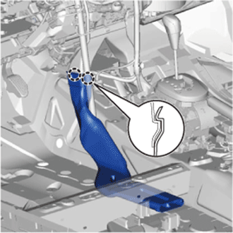
| 6. REMOVE FRONT NO. 1 VENTILATOR SEAL |
Disengage the clamp and remove the front No. 1 ventilator seal.
| 7. REMOVE FRONT AIR SHUTTER SEAL RH |
- HINT:
- Use the same procedure as for the No. 1 ventilator seal.
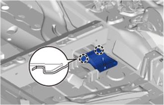
| 8. REMOVE COWL TOP TO COWL INNER BRACE |
Remove the 2 bolts and the inner cowl top to cowl brace.
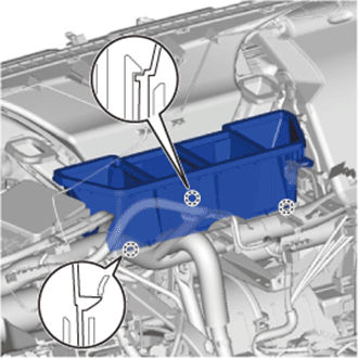
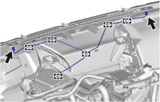
| 9. REMOVE COWL TOP OUTER PANEL |
Disengage the 2 clamps and separate the wire harness.
Remove the 8 bolts and the outer cowl top panel.
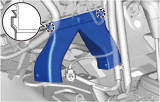
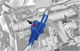
| 10. DISCONNECT AIR CONDITIONER TUBE AND ACCESSORY ASSEMBLY |
Remove the bolt.
Turn the hook connector clockwise and disconnect the air conditioner tube and liquid tube.
Remove the O-ring from the air conditioner tube and liquid tube.
- NOTICE:
- Seal the openings of the disconnected parts using vinyl tape to prevent the entry of moisture and foreign matter.
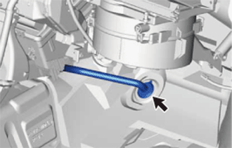
| 11. DISCONNECT HEATER WATER OUTLET HOSE A |
Slide the clip and disconnect the heater water outlet hose from the air conditioning unit.
| 12. DISCONNECT HEATER WATER INLET HOSE A |
Slide the clip and disconnect the heater water inlet hose from the air conditioning unit.
| 13. REMOVE LOWER INSTRUMENT PANEL SUB-ASSEMBLY |
(YARIS_NCP93 RM000001RHJ019X.html)
| 14. REMOVE STEERING COLUMN ASSEMBLY |
(YARIS_NCP93 RM000000UCZ031X.html)
| 15. REMOVE HEATER TO REGISTER DUCT ASSEMBLY |
Disengage the 3 claws and remove the heater to register duct.
| 16. REMOVE DEFROSTER NOZZLE ASSEMBLY |
Disconnect the connectors and disengage the clamps, then disconnect the wire harness.
Disengage the 2 claws and 3 guides and remove the defroster nozzle.
| 17. REMOVE REAR NO. 2 AIR DUCT (for Cold Area Specification Vehicles) |
Open the floor carpet so that the air duct can be removed and installed from the vehicle.
Disengage the 2 claws and remove the air duct.
| 18. REMOVE REAR NO. 4 AIR DUCT (for Cold Area Specification Vehicles) |
Disengage the 2 claws and remove the air duct.
| 19. REMOVE REAR NO. 3 AIR DUCT (for Cold Area Specification Vehicles) |
Disengage the 2 claws and remove the air duct.
| 20. SEPARATE DRAIN COOLER HOSE |
Separate the drain cooler hose.
| 21. REMOVE NO. 1 INSTRUMENT PANEL BRACE SUB-ASSEMBLY (except Cold Area Specification Vehicles) |
Disengage the 2 clamps.
Remove the 2 bolts, nut and screw, then remove the instrument panel brace.
- HINT:
- If the vehicle is equipped with knee airbag, remove the knee airbag bracket mounting bolt.
| 22. REMOVE NO. 1 INSTRUMENT PANEL BRACE SUB-ASSEMBLY (for Cold Area Specification Vehicles) |
Disengage the 2 clamps.
Remove the bolt and disconnect the ground wire.
Remove the 2 bolts, nut and screw, then remove the instrument panel brace.
- HINT:
- If the vehicle is equipped with knee airbag, remove the bolt A.
| 23. REMOVE REAR NO. 1 AIR DUCT (for Cold Area Specification Vehicles) |
Disengage the 2 claws and remove the air duct.
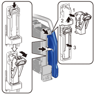
| 24. REMOVE INSTRUMENT PANEL JUNCTION BLOCK ASSEMBLY |
Disengage the clamps.
Disconnect the connectors on the front side.
Remove the bolt and separate the instrument panel junction block.
Disconnect the back side connectors and remove the instrument panel junction block as shown in the illustration.
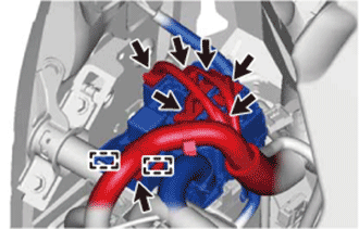
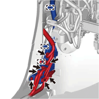
| 25. SEPARATE INSTRUMENT PANEL WIRE |
Disconnect the connectors.
Remove the screw.
Disengage the 2 clamps and separate the connector holder.
Remove the screw and the wire harness protector.
Disconnect the connectors.
Remove the bolt.
Disengage the 3 clamps and remove the connector holder.
Disconnect the 3 connectors.
Disengage the 3 clamps and disconnect the instrument panel wire.
Remove the bolts and disconnect the ground wire.
Disconnect the connectors and clamps, then disconnect the instrument panel wire.
| 26. REMOVE INSTRUMENT PANEL REINFORCEMENT |
Remove the 8 bolts and 3 screws, then remove the instrument panel reinforcement.
| 27. REMOVE AIR CONDITIONER UNIT ASSEMBLY |
Remove the 3 bolts and nut, then remove the air conditioner unit.
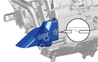
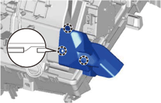
| 28. REMOVE AIR CONDITIONING AMPLIFIER ASSEMBLY |
Remove the screw.
Disengage the claw and remove the air conditioning amplifier as shown in the illustration.
| 29. REMOVE AIR CONDITIONING RADIATOR ASSEMBLY |
Remove the 3 screws and the air conditioning radiator.
| 30. REMOVE NO. 1 AIR DUCT |
Disengage the 3 claws and remove the air duct.
| 31. REMOVE NO. 2 AIR DUCT |
Disengage the 3 claws and remove the air duct.