Theft Deterrent System (For Hatchback) Horn Circuit
DESCRIPTION
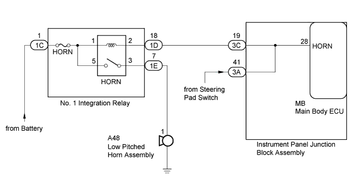
WIRING DIAGRAM
INSPECTION PROCEDURE
INSPECT HORN
INSPECT INSTRUMENT PANEL JUNCTION BLOCK ASSEMBLY
THEFT DETERRENT SYSTEM (for Hatchback) - Horn Circuit |
DESCRIPTION
When the theft deterrent system is switched from the armed state to the alarm sounding state, the main body ECU transmits a signal to cause the horn to sound at intervals of 0.4 seconds.
WIRING DIAGRAM
INSPECTION PROCEDURE
- NOTICE:
- Inspect the fuses for circuits related to this system before performing the following inspection procedure.
Press the horn switch and check if the horns sound.
ResultResult
| Proceed to
|
Horn sound
| A
|
Horn do not sound
| B
|
| 2.INSPECT INSTRUMENT PANEL JUNCTION BLOCK ASSEMBLY |
Remove the main body ECU (YARIS_NCP93 RM000003TOE00CX.html).
Text in Illustration*a
| Component without harness connected
(Instrument Panel Junction Block Assembly)
| -
| -
|
Disconnect the 3C instrument panel junction block assembly connector.
Measure the resistance according to the value(s) in the table below.
- Standard Resistance:
Tester Connection
| Condition
| Specified Condition
|
3C-19 - MB-28 (HORN)
| Always
| Below 1 Ω
|