Meter / Gauge System (For Sedan) Operating Light Control Rheostat Does Not Change Light Brightness
DESCRIPTION
WIRING DIAGRAM
INSPECTION PROCEDURE
READ VALUE USING TECHSTREAM (RHEOSTAT)
INSPECT FUSE (GAUGE)
CHECK HARNESS AND CONNECTOR (FUSE (GAUGE) - LIGHT CONTROL RHEOSTAT)
CHECK HARNESS AND CONNECTOR (MAIN BODY ECU - LIGHT CONTROL RHEOSTAT)
INSPECT LIGHT CONTROL RHEOSTAT
CHECK HARNESS AND CONNECTOR (COMBINATION METER ASSEMBLY - LIGHT CONTROL RHEOSTAT)
METER / GAUGE SYSTEM (for Sedan) - Operating Light Control Rheostat does not Change Light Brightness |
DESCRIPTION
The combination meter assembly controls the combination meter illumination in accordance with the light control signals from the light control rheostat.
WIRING DIAGRAM
INSPECTION PROCEDURE
| 1.READ VALUE USING TECHSTREAM (RHEOSTAT) |
Connect the Techstream to the DLC3.
Turn the ignition switch ON and turn the tester ON.
Select the item below in the Data List, and read the value displayed on the Techstream.
- Body Electrical / Combination Meter / Data List::
Tester Display
| Measurement Item/Range
| Normal Condition
| Diagnostic Note
|
Rheostat value (A/D)
| Rheostat value
Min.: 0
Max.: 255
| Light control rheostat switch is Dark (0)→Bright (255)
| -
|
- OK:
- Light brightness can be changed within the specified range by actual operation.
| OK |
|
|
|
| REPLACE COMBINATION METER ASSEMBLY |
|
Remove the GAUGE fuse from the main body ECU.
Measure the resistance.
- OK:
- Below 1 Ω
Reinstall the GAUGE fuse.
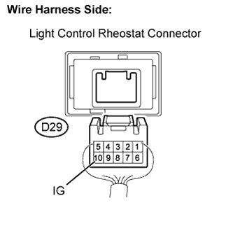
| 3.CHECK HARNESS AND CONNECTOR (FUSE (GAUGE) - LIGHT CONTROL RHEOSTAT) |
Disconnect the D29 light control rheostat connector.
Measure the voltage.
- Standard voltage:
Tester Connection
| Condition
| Specified Condition
|
D29-10 - Body ground
| Ignition switch ON
| 11 to 14V
|
Reconnect the light control rheostat connector.
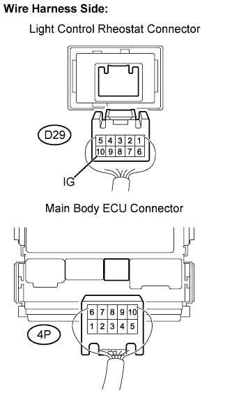
| 4.CHECK HARNESS AND CONNECTOR (MAIN BODY ECU - LIGHT CONTROL RHEOSTAT) |
Disconnect the D29 light control rheostat connector.
Disconnect the 4P main body ECU connector.
Measure the resistance.
- Standard resistance:
Tester
| Condition
| Specified Condition
|
D29-10 (IG)- 4P-1
| Always
| Below 1 Ω
|
Reconnect the light control rheostat connector.
Reconnect the main body ECU connector.
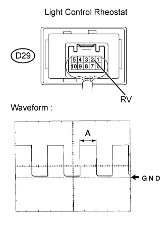
| 5.INSPECT LIGHT CONTROL RHEOSTAT |
Remove the light control rheostat but without disconnecting the connector.
Turn the ignition switch ON.
Using an oscilloscope, check the signal waveform of the light control rheostat.
Item
| Contents
|
Terminal connection
| D29-2 (RV) - Body ground
|
Tool setting
| 5V / DIV, 50ms / DIV
|
Vehicle condition
| Ignition switch ON
|
- OK:
- Waveform is as shown in the illustration.
- HINT:
- Duty ratio changes as the illumination dims. (A becomes longer)
Reinstall the light control rheostat.
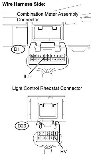
| 6.CHECK HARNESS AND CONNECTOR (COMBINATION METER ASSEMBLY - LIGHT CONTROL RHEOSTAT) |
Disconnect the D1 combination meter assembly connector.
Disconnect the D29 light control rheostat connector.
Measure the resistance.
- Standard resistance:
Tester Connection
| Specified Condition
|
D1-7 (ILL-) - D29-2 (RV)
| Below 1 Ω
|
Reconnect the combination meter assembly.
Reconnect the light control rheostat connector.
| | REPAIR OR REPLACE HARNESS OR CONNECTOR |
|
|