Meter / Gauge System (For Hatchback) -- Terminals Of Ecu |
| CHECK COMBINATION METER ASSEMBLY |

Disconnect the D100 combination meter assembly connector.
Measure the voltage and resistance of the wire harness side connector.
If the result is not as specified, there may be a malfunction in the wire harness.Terminals No. (Symbol) Wiring Color Terminal Description Condition Specified Condition D100-21 (ET) - Body ground W-B - Body ground Ground Always Below 1 Ω D100-39 (IG+) - Body ground P - Body ground Ignition switch signal Ignition switch off → ON Below 1 V → 11 to 14 V D100-40 (B) - Body ground L - Body ground Battery Always 11 to 14 V D101-1 (B) - Body ground R - Body ground Battery Always 11 to 14 V Reconnect the D100 combination meter assembly connector.
Measure the voltage, check for pulse and resistance of the wire harness side connector.
Terminals No. (Symbol) Wiring Color Terminal Description Condition Specified Condition D100-5 (SI) - Body ground L - Body ground Speed signal (Input) Driving at approximately
20 km/h (12 mph)Pulse generation
(See waveform 1)D100-6 (+S) - Body ground SB - Body ground Speed signal (Output) Driving at approximately
20 km/h (12 mph)Pulse generation
(See waveform 1)D100-9 (S) - Body ground Y - Body ground Engine oil pressure signal Engine oil pressure warning light ON → OFF Below 1 V → 11 to 14 V D100-10 (WLVL)*2 - Body ground V - Body ground Washer level warning signal Ignition switch ON Washer level warning light ON → OFF Below 1 V → 11 to 14 V D100-11 (CHK) - Body ground LG - Body ground Check engine warning light signal Check engine warning light ON → OFF Below 1 V → 11 to 14 V D100-12 (SW) - Body ground GR - Body ground Brake fluid level warning light signal Ignition switch ON
Brake fluid level warning light ON → OFFBelow 1 V → 11 to 14 V D100-14 (-) - Body ground BR - Body ground High beam indicator signal (-) Always Below 1 V D100-16 (L) - Body ground G - Body ground Fuel level signal Ignition switch ON
Fuel level is FULL → EMPTYBelow 1 V → 4.5 to 9.0 V D100-17 (TC) - Body ground SB - Body ground TAIL cancel switch signal TAIL cancel switch OFF → ON 10 kΩ or higher → Below 1 Ω D100-19 (+) - Body ground GR - Body ground High beam indicator signal (+) High beam indicator ON → OFF 11 to 14 V → Below 1 V D100-20 (ILL+) - Body ground R - Body ground Taillight signal Light control switch OFF → ON Below 1 V → 11 to 14 V D100-31 (CANL) - Body ground W - Body ground CAN communication line Ignition switch ON Pulse generation D100-32 (CANH) - Body ground G - Body ground CAN communication line Ignition switch ON Pulse generation D100-33 (SW3) - Body ground W - Body ground Light control rheostat switch ground Always Below 1 Ω D100-34 (TX1-) - Body ground B - Body ground Outside temperature signal Ignition switch ON outside temperature 25 °C Approximately 1.3 V D100-35 (TX1+) - Body ground W - Body ground Ground
(Temperature ground)Always Below 1 Ω D100-36 (SW2) - Body ground Y - Body ground Light control rheostat knob input Light control rheostat knob fully turned downward Below 1 Ω Light control rheostat knob fully turned upward 10 kΩ or higher D100-37 (SW1) - Body ground G - Body ground Power source for light control rheostat Ignition switch ON 4.6 to 5.4 V D101-3 (HAZ) - Body ground L - Body ground Hazard warning signal switch signal Hazard warning signal switch off 11 to 14 V Hazard warning signal switch on Below 1 Ω D101-7 (LR) - Body ground V - Body ground Right turn signal Ignition switch ON
Right turn indicator light OFF → ONBelow 1 V → 11 to 14 V D101-9 (ER) - Body ground B - Body ground Turn signal switch RH signal Turn signal switch RH on 11 to 14 V Turn signal switch RH off Below 1 Ω D101-10 (EL) - Body ground Y - Body ground Turn signal switch LH signal Turn signal switch LH on 11 to 14 V Turn signal switch LH off Below 1 Ω D101-12 (FOG)*1 - Body ground BE - Body ground Front fog signal Ignition switch ON
Front fog switch OFF → ONBelow 1 V → 11 to 14 V D101-13 (LL) - Body ground LG - Body ground Left turn signal Ignition switch ON
Left turn indicator light OFF → ONBelow 1 V → 11 to 14 V - *1: w/ Fog Light
- *2: w/ Washer Level Warning
Waveform 1: Using an oscilloscope
Terminal Connections D100-6 (+S) and Body ground
D100-5 (SI) and Body groundTool Setting 5 V/DIV, 20 ms/DIV Condition Driving at approximately 20 km/h (12 mph) - HINT:
- As the vehicle speed increases, the cycle of the signal waveform narrows.

- *1: w/ Fog Light
| CHECK MAIN BODY ECU (MULTIPLEX NETWORK BODY ECU) AND INSTRUMENT PANEL JUNCTION BLOCK ASSEMBLY (2 Connector Type) |
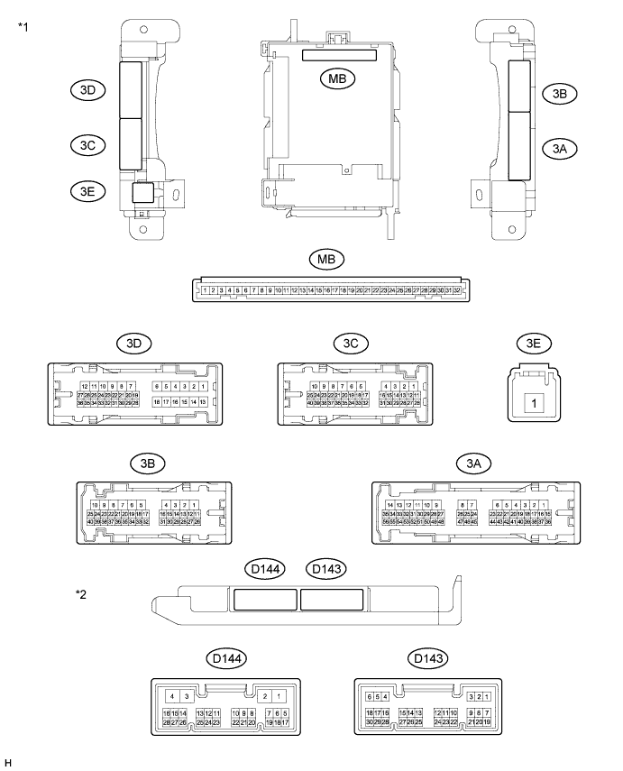
| *1 | Instrument Panel Junction Block Assembly | *2 | Main Body ECU (Multiplex Network Body ECU) |
Remove the main body ECU (multiplex network body ECU) (YARIS_NCP93 RM000003TOE00CX.html).
Measure the resistance and voltage between each terminal of the wire harness side connectors and body ground.
If the result is not as specified, there may be a malfunction on the wire harness side.Terminal No. (Symbol) Wiring Color Terminal Description Condition Specified Condition MB-11 (GND1) - Body ground None - Body ground Ground Always Below 1 Ω MB-29 (ACC) - Body ground None - Body ground Ignition power supply (ACC signal) Ignition switch ACC 11 to 14 V MB-30 (BECU) - Body ground None - Body ground +B (power system signal system) power supply Always 11 to 14 V MB-32 (IG) - Body ground None - Body ground Ignition power supply (IG signal) Ignition switch ON 11 to 14 V Install the main body ECU (multiplex network body ECU) (YARIS_NCP93 RM000003TOC00CX.html).
Measure the voltage between each terminal of the wire harness side connectors and body ground.
If the result is not as specified, there may be a malfunction in the wire harness.Terminal No. (Symbol) Wiring Color Terminal Description Condition Specified Condition 3A-28 (PKB) - Body ground R - Body ground Parking brake signal Parking brake warning light ON → OFF Below 1 V → 11 to 14 V D143-13 (CANL) - Body ground W - Body ground CAN communication line Ignition switch ON Pulse generation D143-14 (CANH) - Body ground R - Body ground CAN communication line Ignition switch ON Pulse generation
| CHECK MAIN BODY ECU (MULTIPLEX NETWORK BODY ECU) AND INSTRUMENT PANEL JUNCTION BLOCK ASSEMBLY (1 Connector Type) |

| *1 | Instrument Panel Junction Block Assembly | *2 | Main Body ECU (Multiplex Network Body ECU) |
Remove the main body ECU (multiplex network body ECU) (YARIS_NCP93 RM000003TOE00CX.html).
Measure the resistance and voltage between each terminal of the wire harness side connectors and body ground.
If the result is not as specified, there may be a malfunction on the wire harness side.Terminal No. (Symbol) Wiring Color Terminal Description Condition Specified Condition MB-11 (GND1) - Body ground None - Body ground Ground Always Below 1 Ω MB-29 (ACC) - Body ground None - Body ground Ignition power supply (ACC signal) Ignition switch ACC 11 to 14 V MB-30 (BECU) - Body ground None - Body ground +B (power system signal system) power supply Always 11 to 14 V MB-32 (IG) - Body ground None - Body ground Ignition power supply (IG signal) Ignition switch ON 11 to 14 V Install the main body ECU (multiplex network body ECU) (YARIS_NCP93 RM000003TOE00CX.html).
Measure the voltage between each terminal of the wire harness side connectors and body ground.
If the result is not as specified, there may be a malfunction in the wire harness.Terminal No. (Symbol) Wiring Color Terminal Description Condition Specified Condition 3A-28 (PKB) - Body ground R - Body ground Parking brake signal Parking brake warning light ON → OFF Below 1 V → 11 to 14 V D143-13 (CANL) - Body ground W - Body ground CAN communication line Ignition switch ON Pulse generation D143-14 (CANH) - Body ground R - Body ground CAN communication line Ignition switch ON Pulse generation
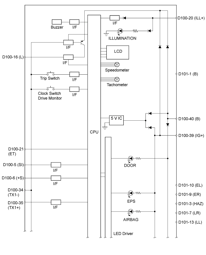
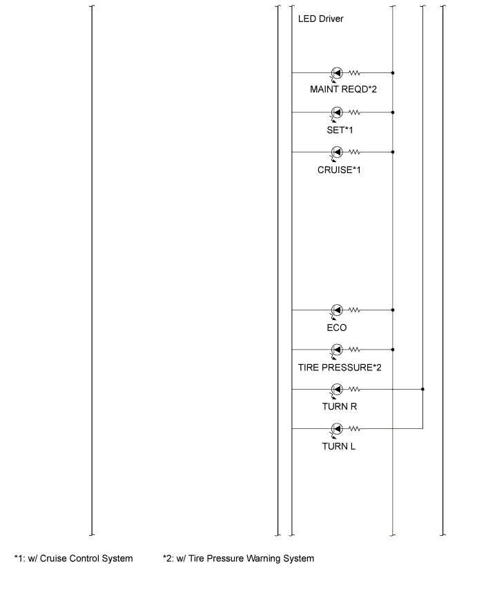
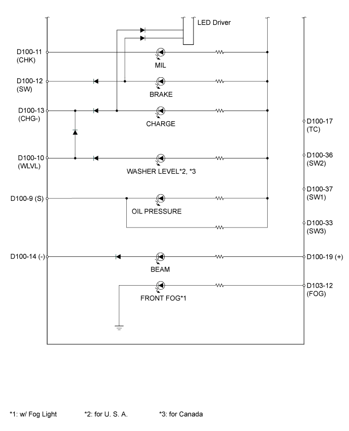
| COMBINATION METER INTERNAL CIRCUIT |

| Terminal No. | Wire Harness Side | |
| 5 | Brake actuator assembly (skid control ECU)*1 or Speedometer Sensor*2 | |
| 6 | Other ECU | |
| 9 | Engine oil pressure switch assembly | |
| 10*4 | Washer level warning switch | |
| 11 | ECM | |
| 12 | Brake fluid level warning switch | |
| 14 | Body ground | |
| 16 | Fuel sender gauge assembly | |
| 17 | Light control rheostat | |
| 19 | H-LP LH HI fuse | |
| 20 | Panel fuse | |
| 21 | Body ground | |
| 31 | CAN communication line | |
| 32 | CAN communication line | |
| 33 | Light control rheostat | |
| 34 | Ambient temperature sensor | |
| 35 | Ambient temperature sensor | |
| 36 | Light control rheostat | |
| 37 | Light control rheostat | |
| 39 | IG2 relay | |
| 40 | Battery | |
| D101 | 1 | Battery |
| 3 | Hazard warning signal switch assembly | |
| 7 | Turn signal light RH | |
| 9 | Headlight dimmer switch assembly (Turn signal switch) | |
| 10 | Headlight dimmer switch assembly (Turn signal switch) | |
| 12 | FR FOG relay*3 | |
| 13 | Turn signal light LH | |
- *1: w/ ABS
- *2: w/o ABS
- *3: w/ Fog Light
- *4: w/ Washer Level Warning